Filter cartridge assembly and method of manufacture thereof

a technology of filter cartridges and components, applied in the direction of filtration separation, separation processes, manufacturing tools, etc., can solve the problems of affecting the manufacture of filter cartridges, water may block the fuel line, and the filter element within the housing may complicate the cartridge manufacturing

Active Publication Date: 2015-06-30
CLARCOR INC
View PDF9 Cites 8 Cited by
  • Summary
  • Abstract
  • Description
  • Claims
  • Application Information

AI Technical Summary

Benefits of technology

[0008]The apparatus and method of the present disclosure provides advantages over and relative to the above discussed prior art. For example, the fuel filter element and associated filter cartridge disclosed herein provides reliable filtration of fuel, and a strong mechanical connection between the cartridge housing and filter element. The mechanical connection between the first end cap and the first shell portion provides strong retention forces, without the need for an adhesive connection between the element and the housing. Furthermore, the method of mounting the fuel filter element within the cartridge streamlines the cartridge manufacturing process and reduces the time required for assembly of a complete product. The disclosed configuration of the filter element and cartridge housing allows for complete pre-manufacture of the filter element before installation of the filter element into the housing, eliminating the use of adhesive within the housing. Other advantages and features of the present invention will become apparent to those skilled in the art from the following detailed description, from the claims, and from the accompanying drawings.

Problems solved by technology

In addition to corroding metal components, water may obstruct the fuel lines when environmental temperatures fall below freezing.
Likewise, abrasive particles may damage sensitive engine components such as the fuel injection pump.
Use of adhesive to secure the filter element within the housing complicates cartridge manufacture.

Method used


Image

  • Filter cartridge assembly and method of manufacture thereof
  • Filter cartridge assembly and method of manufacture thereof
  • Filter cartridge assembly and method of manufacture thereof

Examples


Embodiment Construction

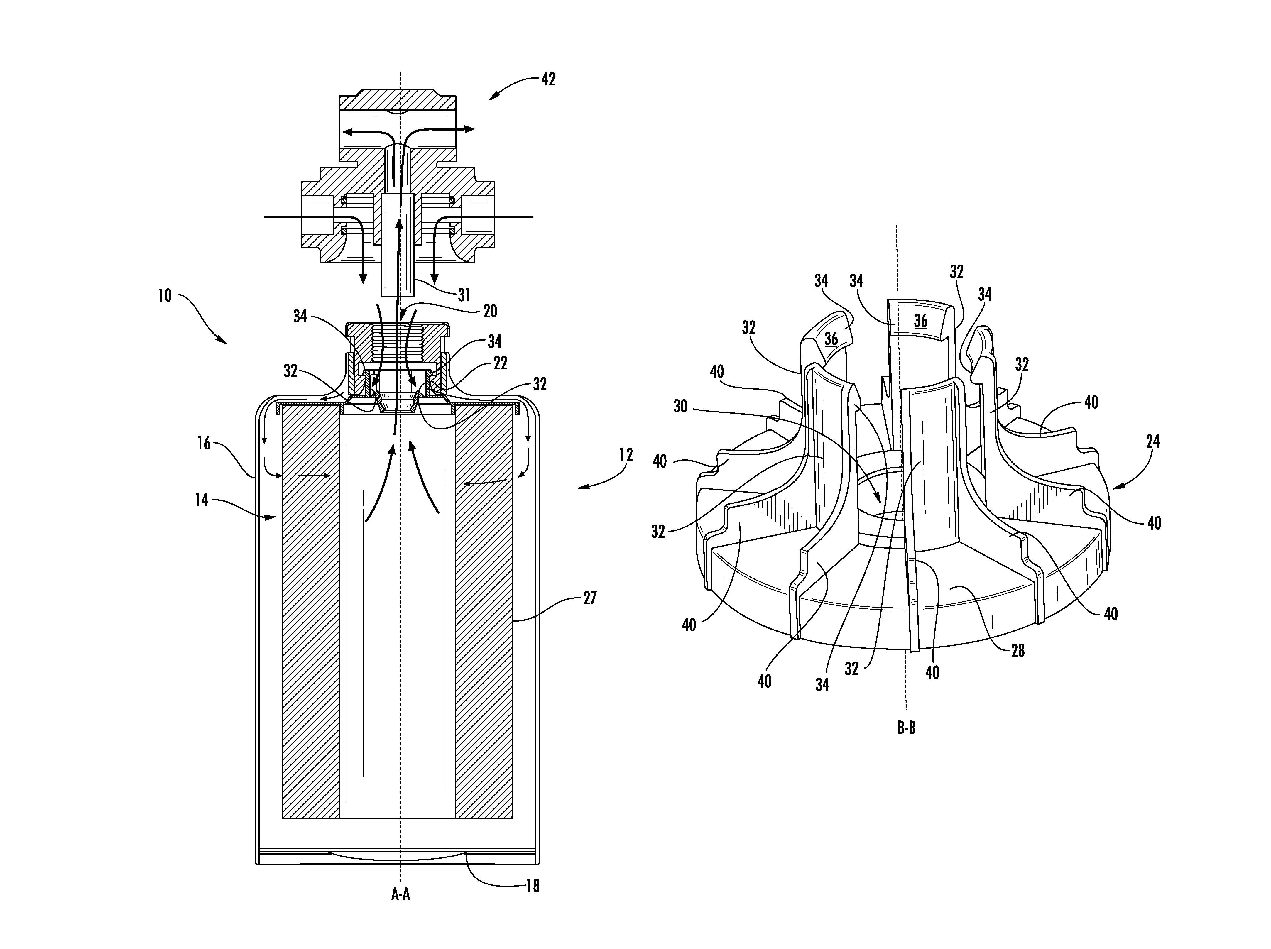
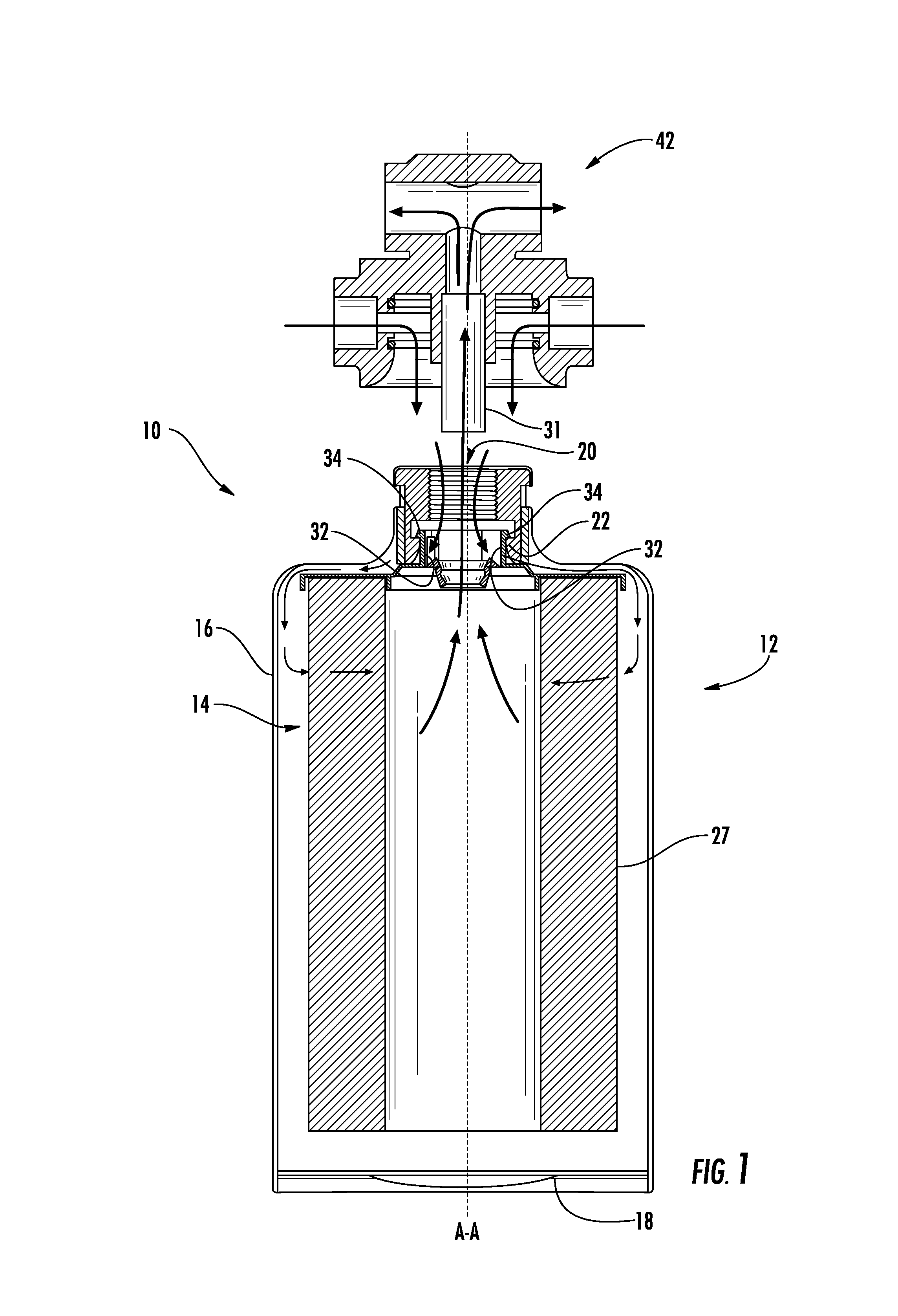
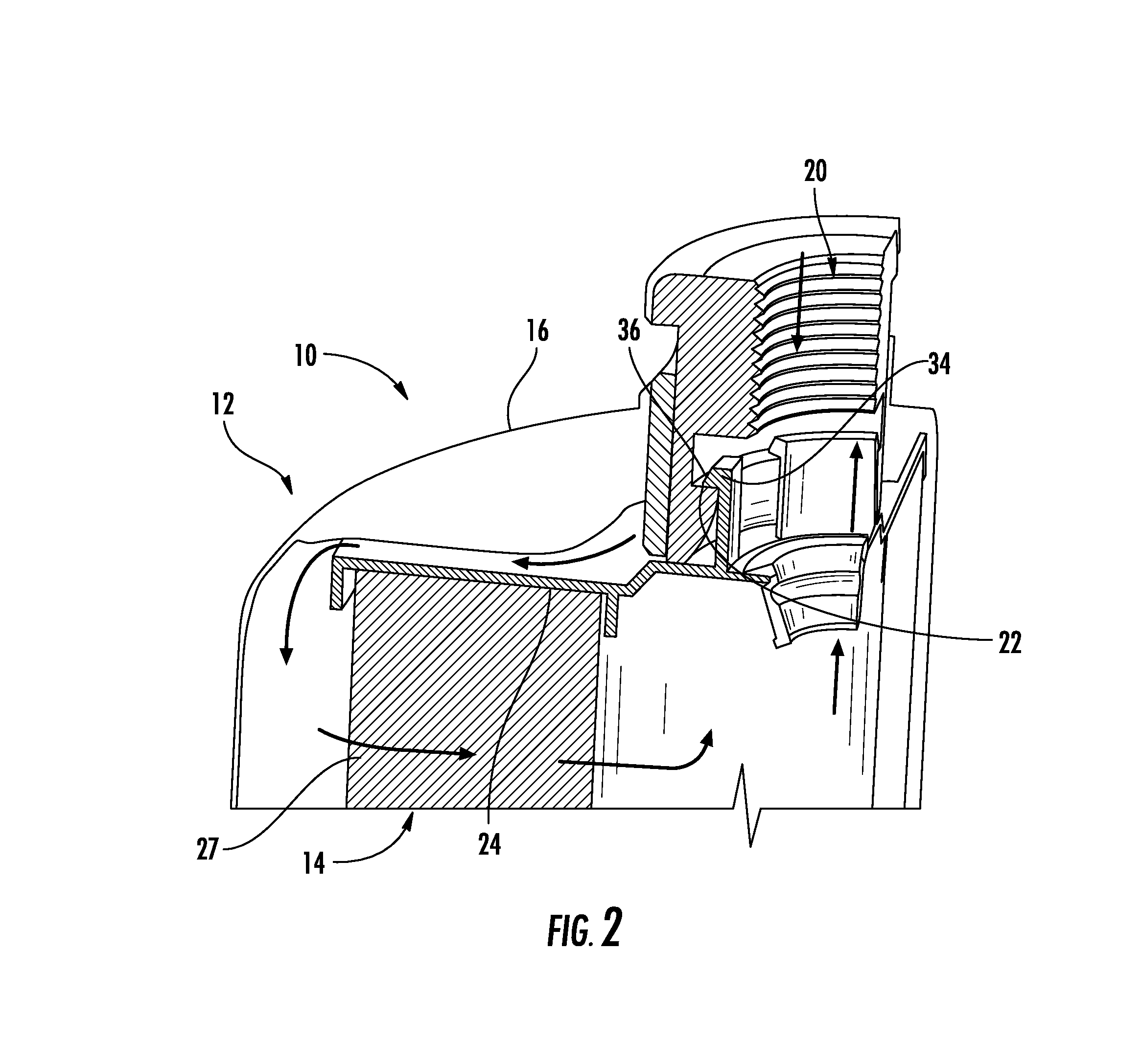
[0017]With reference to the drawings wherein like numerals represent like parts throughout the several figures, a housing 12 and a filter element 14 are provided in connection with the fuel filter cartridge 10 disclosed herein. The filter element 14 is configured to create an improved connection between the cartridge 12 and element 14, in addition to simplifying the cartridge manufacturing process.

[0018]When completely installed, the filter element 14 is suspended within the cartridge housing 12. First (upper) and second (lower) cartridge shell portions (16 and 18 respectively) of the cartridge housing are connected after the filter element 14 is installed within the housing 12, to form a complete filter cartridge 10. As shown in FIG. 1, in one embodiment the first shell portion 16 is a unitary housing which extends the length of the filter cartridge. A second shell portion 18 is attached at an end opposite a cartridge housing opening 20. In an alternate embodiment shown in FIG. 7, ...


PUM

PropertyMeasurementUnit
perimeteraaaaaaaaaa
thicknessaaaaaaaaaa
temperaturesaaaaaaaaaa

Abstract

A filter cartridge has a longitudinal axis. A cartridge housing has first and second shell portions. The first shell portion has a cartridge housing opening and an annular element retention lip which is disposed axially inward of the opening and coaxial with the longitudinal axis. The filter element has a first end cap, a second end cap, and a continuous ring of filter media disposed between the first and second end caps. The first end cap defines a fuel flow port which is coaxial with the longitudinal axis. A plurality of resilient element retention arms extend axially from the first end cap, and surround the fuel flow port. The arms terminate in retention barbs which are mateable with the annular lip. The resilient retention arms hold the retention barbs against the annular lip, suspending the filter element within the cartridge.

Description

BACKGROUND[0001]This disclosure relates generally to devices for filtering and separating liquids. More particularly, the present invention relates to fuel filters for removing foreign particles and separating water from fuel in an internal combustion engine.[0002]It is well-documented that significant quantities of contaminants such as water and various abrasive particles are found in diesel fuel. In addition to corroding metal components, water may obstruct the fuel lines when environmental temperatures fall below freezing. Likewise, abrasive particles may damage sensitive engine components such as the fuel injection pump.[0003]Fuel filter cartridges are a well-known solution for removing water and abrasive particles from diesel fuel before the fuel is pumped into sensitive engine systems. Prior art fuel filter cartridges typically have a housing which defines an axial opening at one end thereof to provide fuel communication between the fuel delivery system and a filter element di...

Claims


Application Information

Patent Timeline
Patent Type & Authority Patents(United States)
IPC IPC(8): B01D29/00B01D29/21B01D29/05
CPCB01D29/21Y10T29/49826B01D2201/291B01D2201/305B01D2201/4084
Inventor MOORE, JONATHAN D.PRIBANIC, JUSTIN R.SASUR, TIMOTHY M.
Owner CLARCOR INC
Why Eureka
Try Eureka