
Monitoring method and camera

a technology applied in the field of monitoring method and camera, can solve the problems of difficulty for the user to keep track of other users, and achieve the effect of increasing robustness and easy adapting the determination of the key position

Active Publication Date: 2015-06-30
AXIS
View PDF2 Cites 0 Cited by
  • Summary
  • Abstract
  • Description
  • Claims
  • Application Information

AI Technical Summary

Benefits of technology

The patent describes a way to efficiently and non-intrusively monitor an area around a counter in a flexible way. This method allows for the creation of rules that only allow certain objects with certain properties access to certain areas. This can be adapted to different monitoring scenarios and practical implementations. Additionally, the method can be tailored to detect suspicious objects by setting a key position based on the detected parts of the object using a cascade of object classifiers. This would make it easy to adapt to different monitoring scenarios.

Problems solved by technology

When the person working at the desk or counter is serving a customer, it might be difficult for him or her to keep track of other persons approaching the desk and potentially trying to gain access to items and equipment only meant to be handled by the person working at the counter.

Method used


Image

  • Monitoring method and camera
  • Monitoring method and camera
  • Monitoring method and camera

Examples


Embodiment Construction

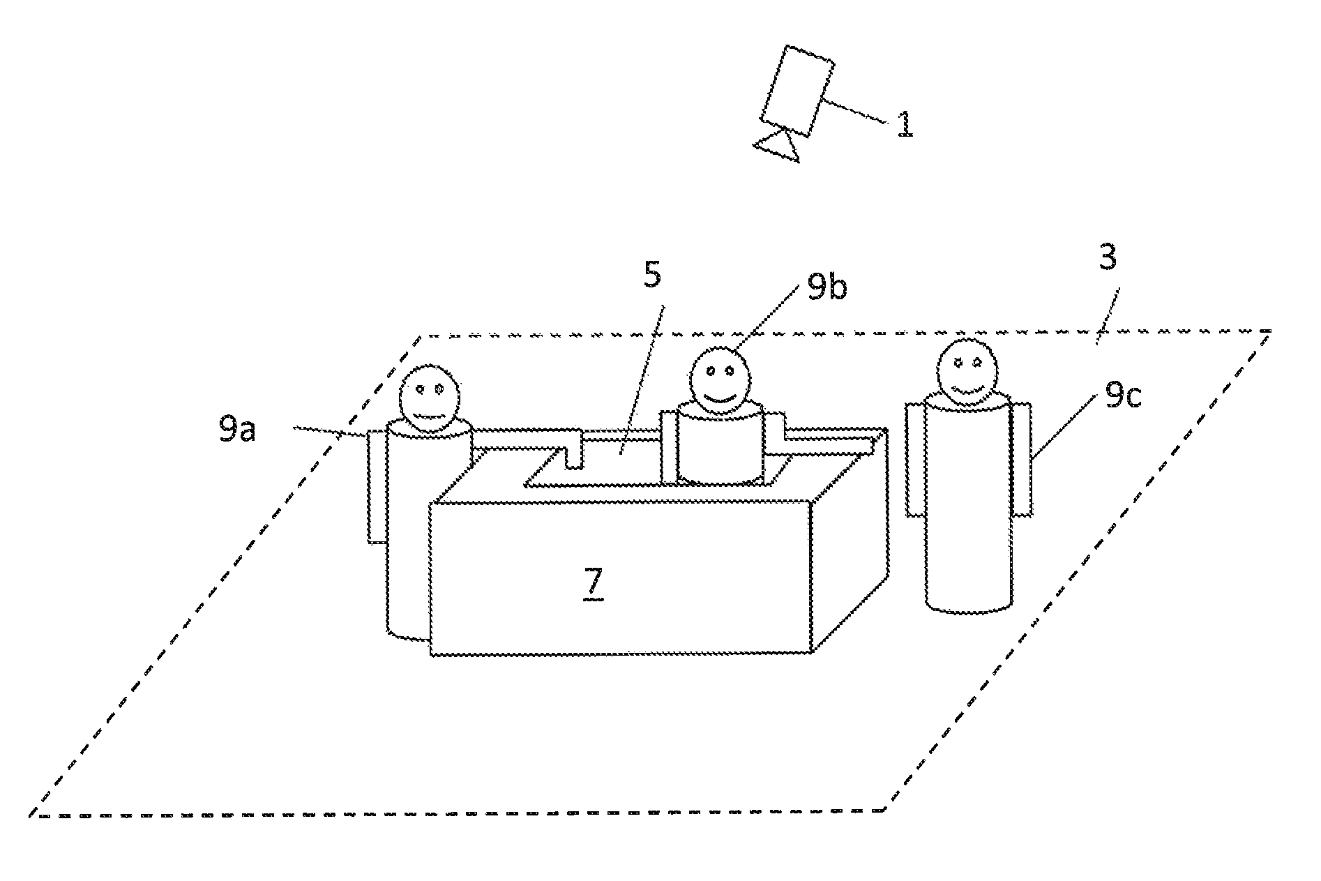
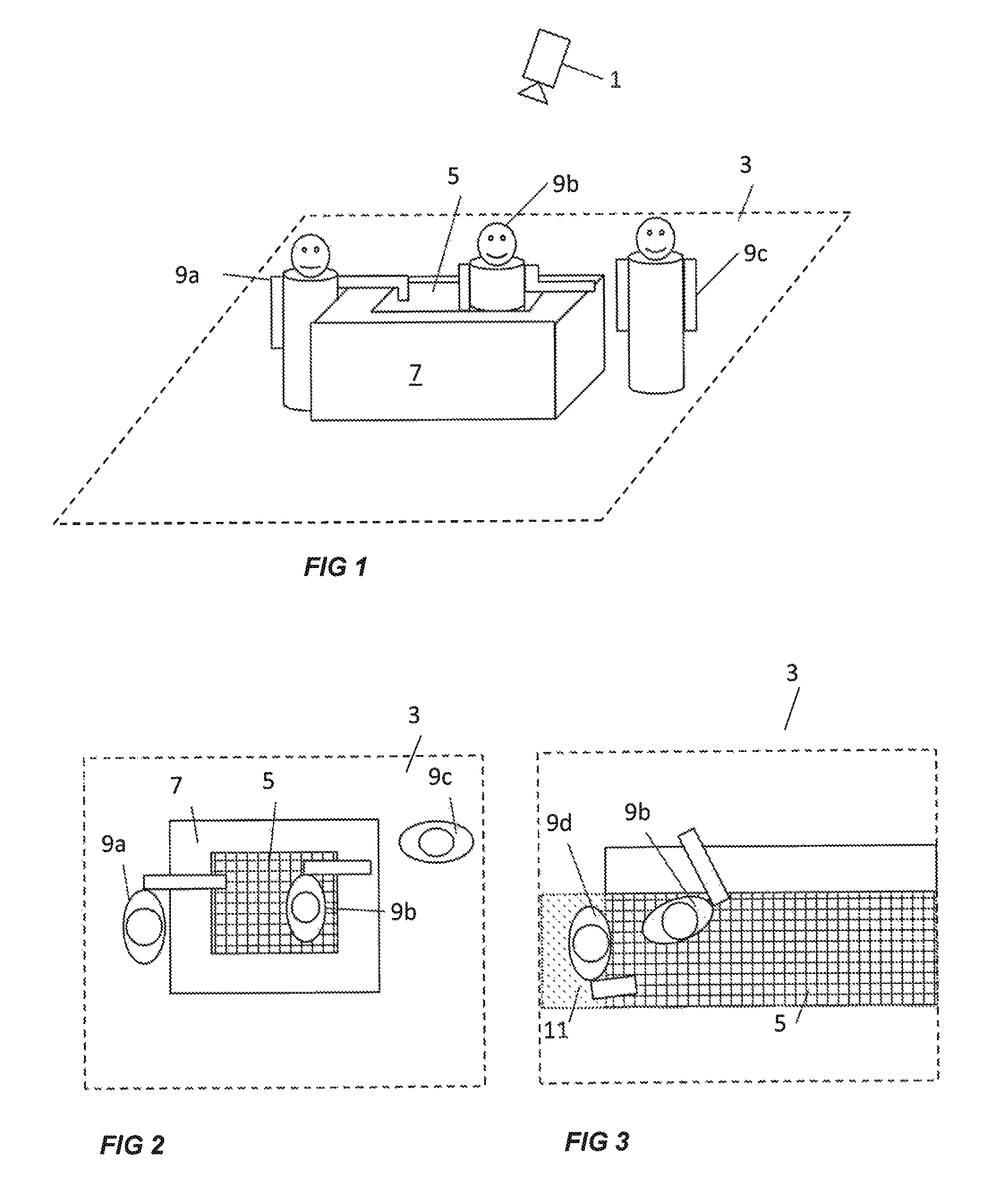
[0033]FIG. 1 illustrates an exemplifying situation where a monitoring camera 1 is arranged to monitor an area 3. The monitoring camera 1 could symbolize a group of monitoring cameras with differing imaging capabilities or a camera including several image sensors. The camera or cameras may e.g. include an image sensor capturing visible light images, a thermal sensor producing images of the temperature within the monitored area, or an image sensor capturing three-dimensional images, e.g. a TOF, time-of-flight, image sensor which gives an image of distance to different pixels, from which it is possible to calculate the depth or height of the monitored area and objects therein.

[0034]The monitored area 3 includes a protected zone 5, in the illustrated example defined by a physical element 7, e.g. in the form of a counter. Objects 9a, 9b, and 9c are present within the monitored area 3. FIG. 2 is a view from above of the situation illustrated in FIG. 1. In other words, FIG. 2 schematically...


PUM


Abstract

A method and a system is provided for monitoring an area by a monitoring camera (1). A protected zone (5) is defined within the monitored area (2) and a suspicious object (9a, 9b) is detected as an object present both inside and outside the protected zone. A key position of the suspicious object is determined, and it is determined if the key position is inside or outside the protected zone (5). If the key position is outside the protected zone a first action is triggered.

Description

CROSS REFERENCE TO RELATED APPLICATION[0001]This application claims the benefit of EPC Application No. 12192217.3, filed Nov. 12, 2012 and U.S. provisional application No. 61 / 726,812, filed Nov. 15, 2012, which are incorporated herein by reference as if fully set forth.TECHNICAL FIELD[0002]The present invention relates to a method and a system for monitoring an area by a monitoring camera.BACKGROUND[0003]Surveillance cameras are currently used in many different applications, for monitoring environments both indoors and outdoors. Cameras may e.g. be used for monitoring areas where a person is serving customers from behind a counter, and where the inside of the counter may be used as storage for items or equipment where access should be restricted to the person manning the counter. Examples of such environments could be hotel front desks, bank office counters, reception desks, bars, fast food counters, cashier desks at gas stations, or check-in counters at airports. Another example is...

Claims


Application Information

Patent Timeline
Patent Type & Authority Patents(United States)
IPC IPC(8): H04N7/18G06K9/00G08B13/196
CPCG06K9/00771G08B13/19613G08B13/19652G08B13/1968G06V20/52G06T7/00H04N7/18
Inventor GUSTAFSSON, DANIELSAGEFALK, WILLYKAHRSTROM, JONATANTRAFF, GUSTAV
Owner AXIS
Features
  • Generate Ideas
  • Intellectual Property
  • Life Sciences
  • Materials
  • Tech Scout
  • Unparalleled Data Quality
  • Higher Quality Content
  • 60% Fewer Hallucinations
Learn More