Gas burner

a burner and gas technology, applied in the direction of combustion process, combustion ignition, heating fuel, etc., can solve the problems of difficult to provide a burner, inability to maintain the air/gas mixture uniformly over all the outlet passages, etc., and achieve the effect of stable combustion

Active Publication Date: 2015-07-07
ELECTROLUX HOME PROD CORP NV
View PDF33 Cites 27 Cited by
  • Summary
  • Abstract
  • Description
  • Claims
  • Application Information

AI Technical Summary

Benefits of technology

[0011]The gas cooking zone preferably comprises a first flame crown for the low power burner unit, a second flame crown for the high power burner unit and an upper cap, which are coaxially arranged one above the other and define the venturi pipes and the gas outlet passages of the two burner units. The flame crowns and the upper cap preferably have an essentially circular disc-shape. The air / gas-mixture leaving the upper flame crown of the high power burner unit can be ignited by the flames of the lower flame crown of the low power burner unit. Therefore, it is only necessary to provide the low power burner unit with a spark plug. Moreover, the entire air / gas-mixture leaving the upper flame crown of the high power burner unit is automatically inflamed by the flames of the low power burner unit. Thus, an inhomogeneous release of the air / gas-mixture from the upper flame crown of the high power burner unit cannot lead to partially extinguished flames. Moreover, the tendency of the flames of the high power burner unit to lift from the upper flame crown is prevented by the presence of the flames of the lower flame crown.
[0013]Preferably, the diameter of the upper cap is larger than the ones of the flame crowns and the upper cap is circumferentially provided at its bottom with a downwardly extending ring-shaped projection or emboss. This emboss stabilizes the combustion of the air / gas-mixture leaving the flame crown of the high power burner unit. It prevents the air / gas-mixture from immediately lifting up from the flame crown of the high power burner unit.
[0015]The gas burner advantageously comprises an ignition spark plug, wherein the first flame crown, the second flame crown and the upper cap define a spark plug supply path for feeding a gas / air-mixture to the spark plug. Moreover, the gas burner preferably comprises a thermocouple, wherein in particular the first flame crown, the second flame crown and the upper cap define a thermocouple supply path for feeding a gas-air-mixture and thus a flame to the thermocouple. In case the combustion is stopped by incident, the continued outflow of the air / gas-mixture poses a threat to people and has to be prevented either by stopping the outflow of the air / gas mixture or by re-lighting the ejected air / gas mixture. The thermocouple allows the detection of the combustion of the air / gas mixture by means of detecting the combustion heat.
[0017]The temperature sensor is preferably arranged in a through hole, which extends through the center of the first flame crown, the second flame crown and the upper cap. In order to further increase the accuracy of the measurement of the temperature sensor, the upper cap can comprise an upwardly projecting, ring-like portion surrounding the temperature sensor and acting as a heat screen for protecting the sensor from heat radiated from the burner units.
[0021]The air / gas-mixture released from the high power burner unit is preferably ignited by the flame of the low power burner unit. Accordingly, a spark plug has to be provided only for the low power burner unit. Moreover, the flames of the low power burner unit can help to generate a stable combustion of the air / gas-mixture released from the high power burner unit, especially when the high power burner unit is operated at its minimum power. Since the entire air / gas mixture leaving the outlet unit of the upper burner unit is automatically ignited by the flames of the lower power burner unit, an inhomogeneous release of the air / gas-mixture from the outlet unit of the upper burner unit will not lead to partially extinguished flames of the upper burner unit. Moreover, the presence of the flames of the lower flame crown of the low power burner unit suppress the tendency of the flames of the upper flame crown of the high power burner unit to lift from the upper flame crown.

Problems solved by technology

However, when the gas flow rate is reduced beyond a critical lower limit, the release of the air / gas-mixture cannot be maintained uniformly over all those outlet passages.
Due to the fact that the maximum and the minimum power of a burner depend from each other, it is hardly possible to provide a burner with a wide power range that enables an operation at very high as well as at very low power.

Method used


Image

  • Gas burner
  • Gas burner
  • Gas burner

Examples


Embodiment Construction

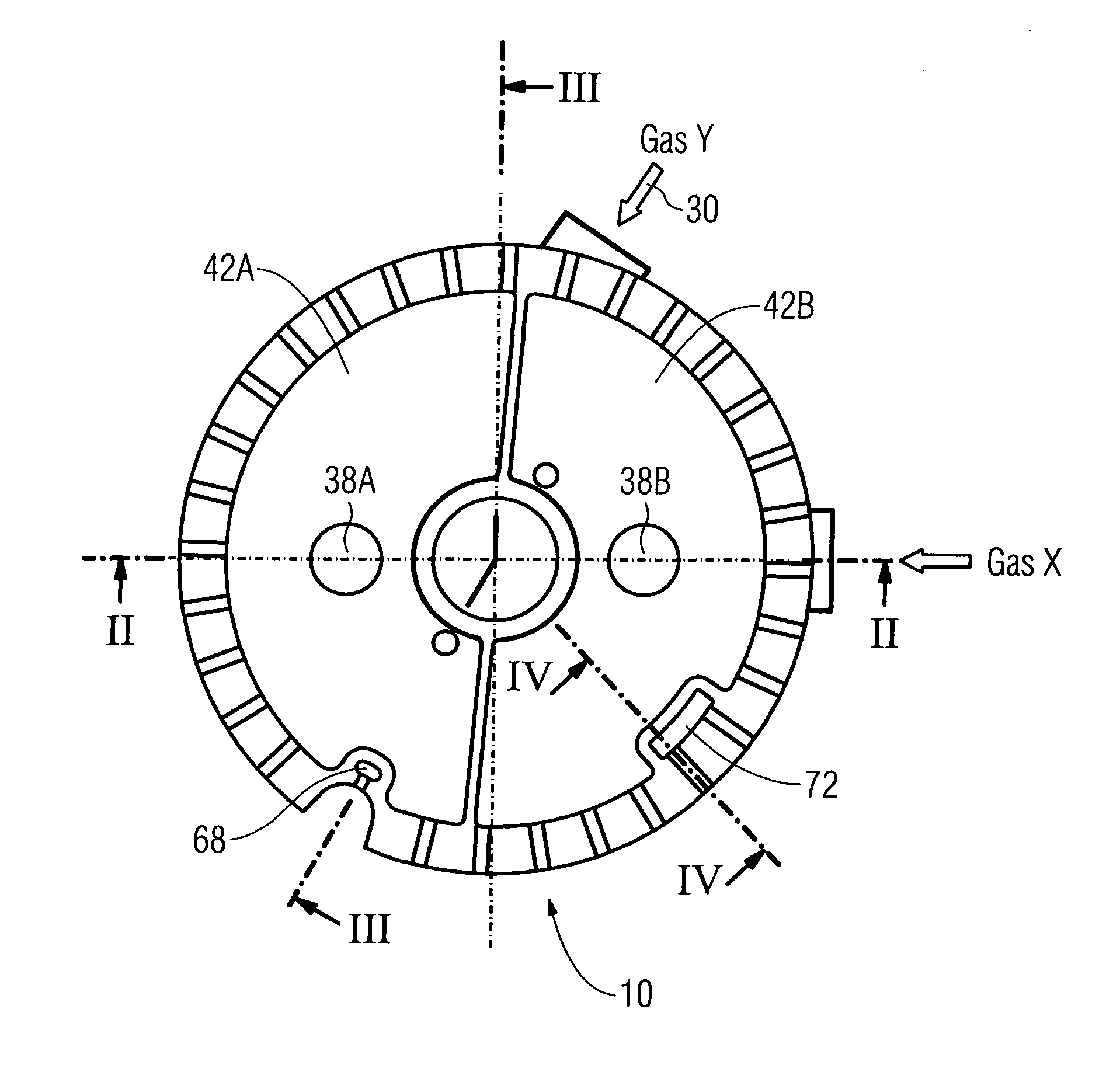
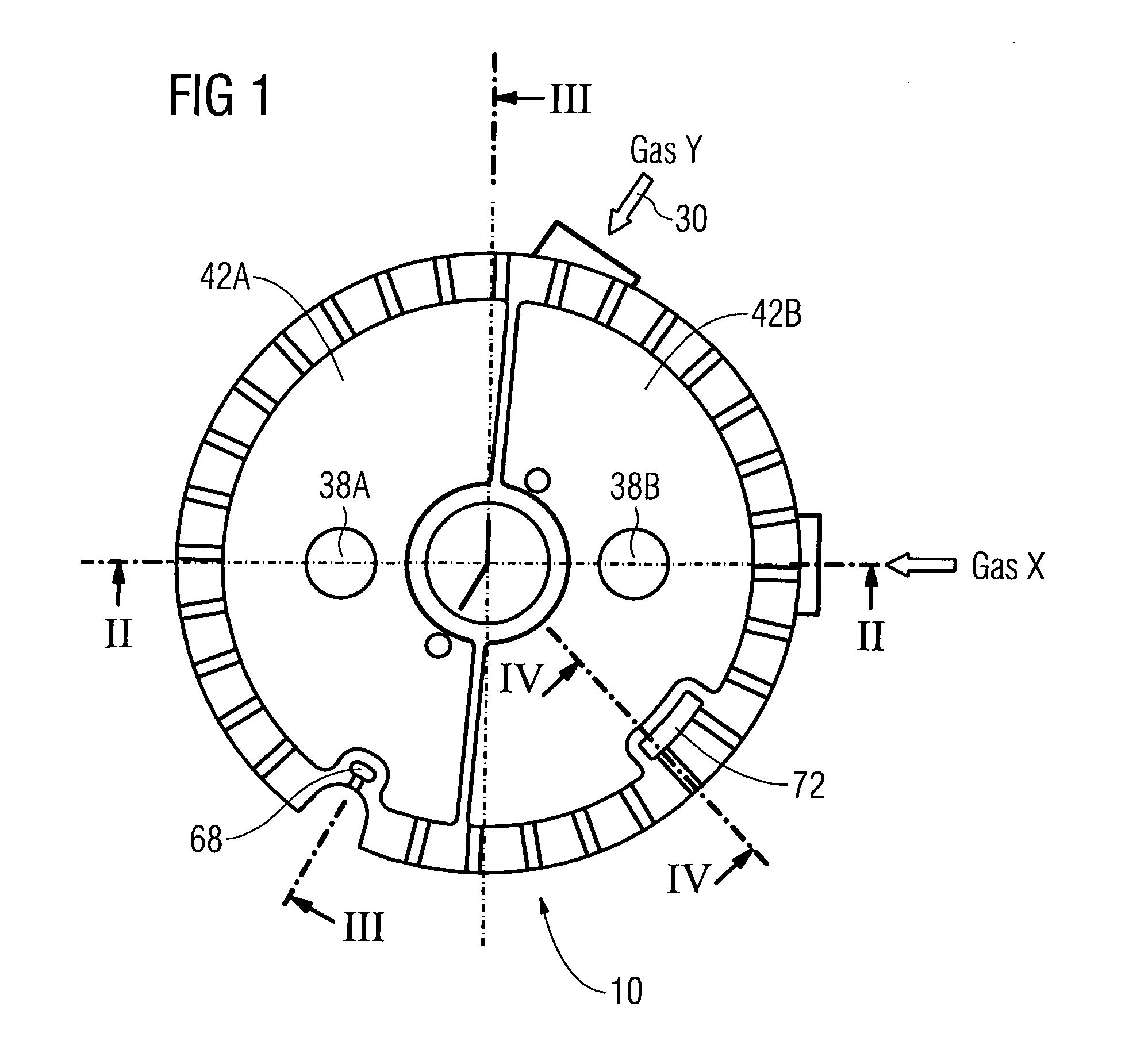
[0033]Below, one embodiment of the present invention will be described with reference to the figures. In the figures, like parts are denoted by like reference numbers.

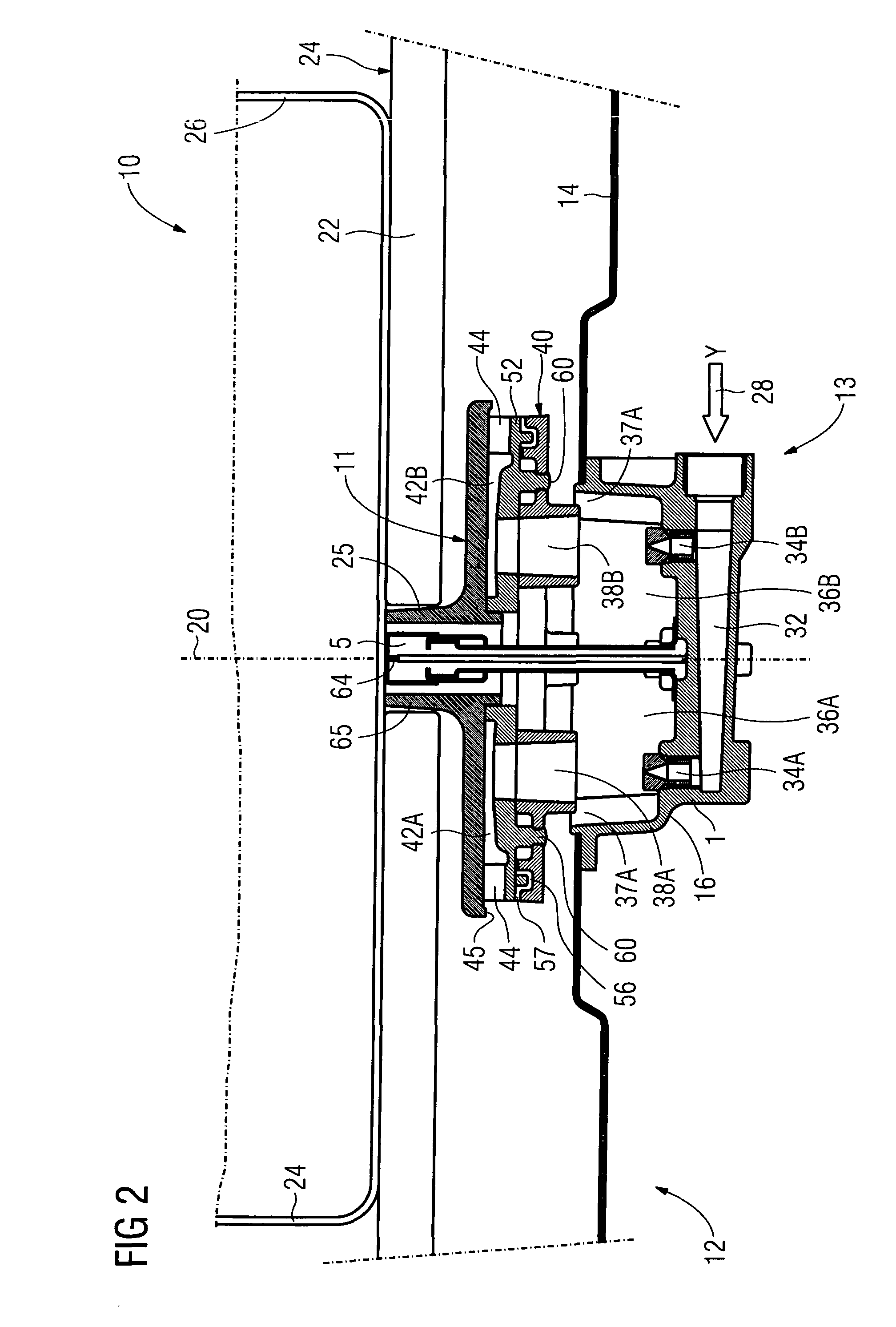
[0034]The gas burner 10 shown throughout the figures is one of a plurality of gas burners of a gas appliance 12 according to the invention. The gas burner 10 comprises a burner arrangement 13, which is received in a base plate 14 forming the top side of a cabinet of the gas appliance 12. The burner unit arrangement 13 is formed by a high power burner unit 16 and a low power burner 18, which are arranged around a common vertical axis 20. Moreover, the gas appliance 12 comprises a supporting structure 22 defining a flat, horizontally extending upper surface 24 for receiving a cooking recipient 26 thereon, as it is shown in FIG. 2.

[0035]The burner units 16 and 18 are supplied with a combustion gas by means of a main pipe (not shown in the figures), which branches to a first branch pipe 28 leading gas to the high power bur...


PUM


Abstract

The invention provides a gas burner (10) with a high power burner unit and a low power burner unit.

Description

TECHNICAL FIELD[0001]The invention relates to a gas burner comprising a burner unit, to a gas appliance comprising one or more of such gas burners, and to a method for operating such a gas burner.BACKGROUND TECHNOLOGY[0002]Conventional gas cookers comprise a cooking field having several cooking zones, e.g. two, three or four cooking zones. Each cooking zone comprises a gas burner for heating a cooking recipient placed thereon, such as a cooking pot, a pan, etc. The gas burner comprises a gas inlet for supplying gas, a mixing device, e.g. in the form of a venturi pipe, for mixing the supplied gas with ambient air, and a plurality of outlet passages formed in a so-called flame crown for releasing the air / gas-mixture for subsequent combustion. Moreover, gas cookers are typically provided with a spark plug for igniting the air / gas-mixture leaving the flame crown, and with a supporting structure arranged above the burners for receiving cooking recipients thereon.[0003]The gas burner of s...

Claims


Application Information

Patent Timeline
Patent Type & Authority Patents(United States)
IPC IPC(8): F24C3/10F23D23/00F23D14/06
CPCF23D14/065F23D23/00F23D2207/00F23D2208/00F23D2208/10F23D2900/14062F23D2900/14063F23N2025/16F23N2037/10F23D14/06F23N2225/16F23N2237/10
Inventor ARMANNI, PIERO
Owner ELECTROLUX HOME PROD CORP NV
Why Eureka
Try Eureka