Average pitot tube type flow meter

a flow meter and pitot tube technology, applied in the direction of fluid speed measurement, speed/acceleration/shock measurement, instruments, etc., can solve the problems of inconvenient installation of rectifying devices, limit in installation, and difficulty in manufacturing total pressure tubes and static tubes integrated to one body, and achieve easy manufacturing and high degree of freedom of installation

Inactive Publication Date: 2015-07-07
DAE HAN INSTR
View PDF9 Cites 1 Cited by
  • Summary
  • Abstract
  • Description
  • Claims
  • Application Information

AI Technical Summary

Benefits of technology

[0010]The first purpose of the present invention is to provide a pitot-tube type flow meter where the straight run is not necessary so that the degree of freedom in installation is enhanced and inconvenience to additionally install the rectifying device is eliminated so that it is easy to install.
[0011]The second purpose of the present invention is to provide a pitot-tube type flow meter where the straight run is not necessary so that the degree of freedom in installation is enhanced, inconvenience to additionally install the rectifying device is eliminated so that it is easy to install, and the total pressure tube and the static pressure tube are separately formed so that it is easy to manufacture.
[0024]According to the present invention, the straight run is not necessary and the degree of freedom for its installation is very high. The rectifying device is integrated thereinto and the inconvenience to install the rectifying device separately is eliminated. Further, the total pressure tube and the static pressure tube can be mounted as they are spaced from each other and it becomes easy to manufacture.

Problems solved by technology

However, even if the rectifying device is used, the straight run is still necessary.
So, there remains the limit in the installation and inconvenience to install the rectifying device in advance of the pitot-tube type flow meter as well as to install the pitot-tube type flow meter.
However, there is a problem that it is not easy to manufacture the total pressure tube and the static tube integrated to one body.

Method used


Image

  • Average pitot tube type flow meter
  • Average pitot tube type flow meter
  • Average pitot tube type flow meter

Examples


Embodiment Construction

[0031]The preferred embodiments of the present invention are described with reference to the accompanying drawings.

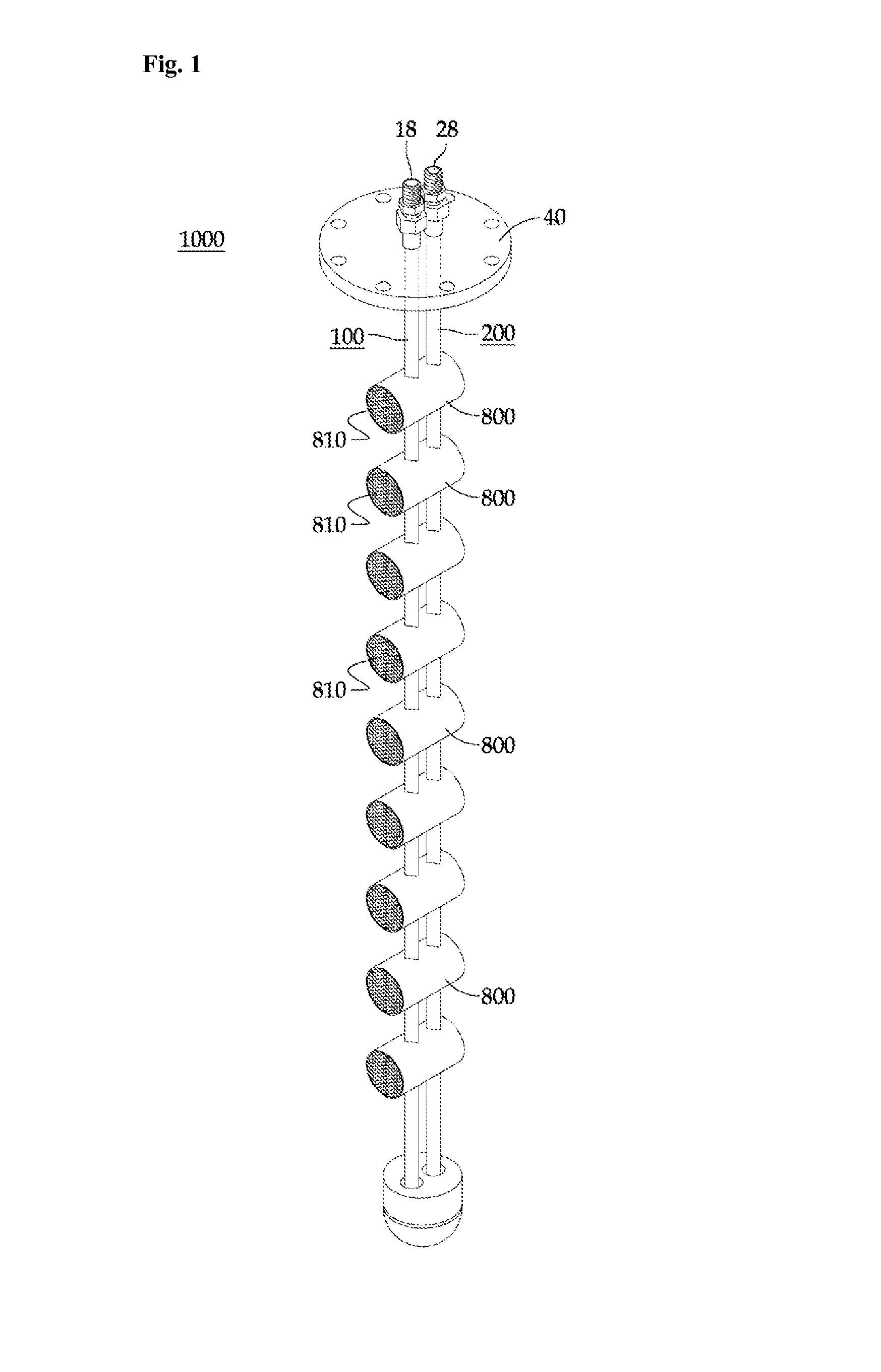
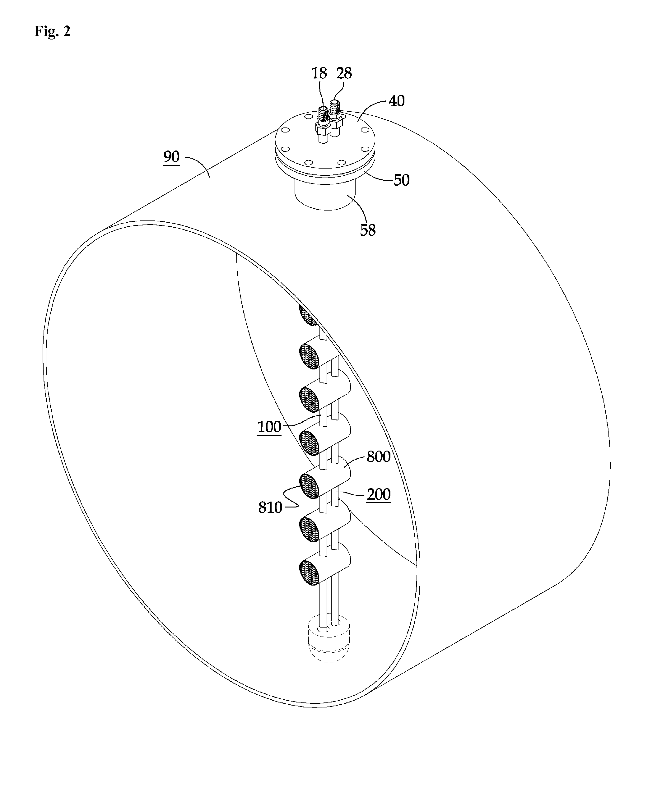
[0032]FIG. 1 shows an average pitot-tube type flow meter 1000 according to an embodiment of the present invention and FIG. 2 shows that the average pitot-tube type flow meter 1000 is installed in a pipe 90.

[0033]As shown, a total pressure tube 100 and a static pressure tube 200 are provided and they have a plurality of total pressure holes 108 and a plurality of static pressure holes 208 along their longitudinal directions, respectively (refer to FIGS. 3 and 4).

[0034]The total pressure tube 100 and the static pressure tube 200 are installed along the direction perpendicular to fluid flow.

[0035]Each of the total pressure tube 100 and the static pressure tube 200 has a valve (not shown) through connection pipes 18 and 28, and they are connected to a differential pressure gauge (not shown) and the difference (dynamic pressure) between the pressure formed in the total press...


PUM


Abstract

Average pitot-tube type flow meter according to the present invention has a total pressure tube and a static pressure tube. The total pressure tube and the static pressure tube are spaced from each other. Across the total pressure tube and the static pressure tube, a rectifying device and a connection case are installed as they are integrated into one body. The rectifying device is positioned in advance of total pressure holes and the total pressure hole and a static pressure hole are positioned inside the connection case.

Description

BACKGROUND OF THE INVENTION[0001]The present invention relates to an average pitot-tube type flow meter and, more particularly, to the average pitot-tube type flow meter that does not require straight run so that the degree of freedom for its installation is enhanced.[0002]When an average pitot tube type flow meter is mounted on a pipe, the water flow in advance of and behind the average pitot-tube type flow meter should be stabilized so that straight runs are required in advance of and behind the average pitot-tube type flow meter.[0003]If it is difficult to secure the straight run length, a rectifying device can be installed to reduce the straight run length.[0004]The rectifying device has a multiple of tubes arranged in parallel one another and the section of the tube can have various shapes. Such a rectifying device is defined in ISO 516701 and so on.[0005]As the fluid passes the plural tubes arranged in parallel one another in the rectifying device, the distribution of the velo...

Claims


Application Information

Patent Timeline
Patent Type & Authority Patents(United States)
IPC IPC(8): G01F1/46G01P5/165
CPCG01P5/165G01F1/46G01F15/00G01F15/18
Inventor HAN, SANG HIESONG, SEUNG JUNE
Owner DAE HAN INSTR
Why Eureka
Try Eureka