Inverse signal transformation

a signal transformation and signal technology, applied in the field of inverse signal transformation, can solve the problems of inherently unstable dplls, highly unpredictable time delay variations, and many applications, and achieve the effects of high unreliability of conventional dppl configurations and inherently unstable dplls

Inactive Publication Date: 2015-07-07
BOGDAN JOHN W
View PDF5 Cites 12 Cited by
  • Summary
  • Abstract
  • Description
  • Claims
  • Application Information

AI Technical Summary

Benefits of technology

[0171]Such DRRS PAM can be useful in less demanding PAM systems with lower numbers of amplitude levels (such as two or four levels) and / or low inter-symbol interference (ISI) and / or crosstalk,
[0975]Such redundancy enables using statistical and deterministic filtering methods, much more efficient than DFT / FFT averaging effect, for selecting the half-cycle supplying most reliable and accurate tone parameters.

Problems solved by technology

However the conventional DPLL configurations have four major limitations listed below:1. DPLLs are inherently unstable if said timing reference comprises components having frequencies higher than ⅕ of the DPLL bandwidth.
Since time stamp messages are sent over regular communication links they are subjected to highly unpredictable time delay variations (TDVs) resulting from collisions between different packet streams sharing a common communication line.
Resulting stability problems cause such conventional DPPL configurations to be highly unreliable in many applications.2. Conventional digital phase detectors and said software algorithms minimizing phase errors, involve accumulation of phase digitization errors.
Such accumulation causes an uncontrolled phase drift of the output clock, when a software error minimization procedure is unable to recognize and eliminate persistent existence of an digitization error corresponding to a lasting unknown frequency error of the output clock.3. Conventional digital phase detectors; offer resolutions worse than that of phase steps limited by maximum clock frequency of IC technology, and they require complex processing for calculating precise phase skews when highly irregular edges of a reference timing are defined in newly emerging timing protocols such as IEEE 1588.
Similarly clock synthesizers have phase steps resolutions bounded by maximum clock frequency of IC technology and furthermore they use frequency synthesis method unable to provide high precision control of phase transients of synthesized clock.4. Conventional clock synchronization systems require expensive local oscillators, expensive external off-chip analog components, and expensive IC technologies suitable for mixed mode operations; in order to provide highly stable and low jitter synchronization clocks required in industrial control systems and in communication networks.
However in conventional solutions; low cost highly stable crystal cuts can not be used, since their oscillation frequencies are to low to be transformed into a stable low jitter clock.
Since said frequency synthesizers use over 10 times slower phase processing and introduce unknown numbers of 10 times less accurate phase steps than the PS, they are unable to perform any phase synthesis and produce uncontrolled phase transients during frequency switching and introduce much more jitter than the PS.
Insufficient accuracy of conventional synchronization for OFDM receivers impose major limitations on OFDM communication quality (see Cit.
[1] and [2] listed below) and such limitations are compounded by rapidly growing data rates.
However such use of preambles or pilots; reduces system efficiency by using signal power that could otherwise have been used for transmitting data, and allows limited accuracy only due to such detection and estimates sensitivity to channel interference and insufficient data supplied in the preamble.
However; as such pilot-less technique uses statistical methods and depend on transmitted data patterns, they are even less accurate than those using preambles or pilots.
Fundamental deficiency of conventional solutions characterized above is their inability to perform any accurate measurement of frequency offset; due to their reliance on using phase offset observed over single preamble / pilot period only for the frequency offset estimation.
Such estimates degraded by unpredictable OFDM channel interference, can not be helped enough by averaging them for as long as each estimate is calculated over single preamble / pilot.
Still other significant deficiency of conventional synchronization is instability of their phase locked loops (used for phase and frequency tracking), caused by changing data patterns and / or unpredictable phase error components introduced into OFDM channel by generally unknown interference.
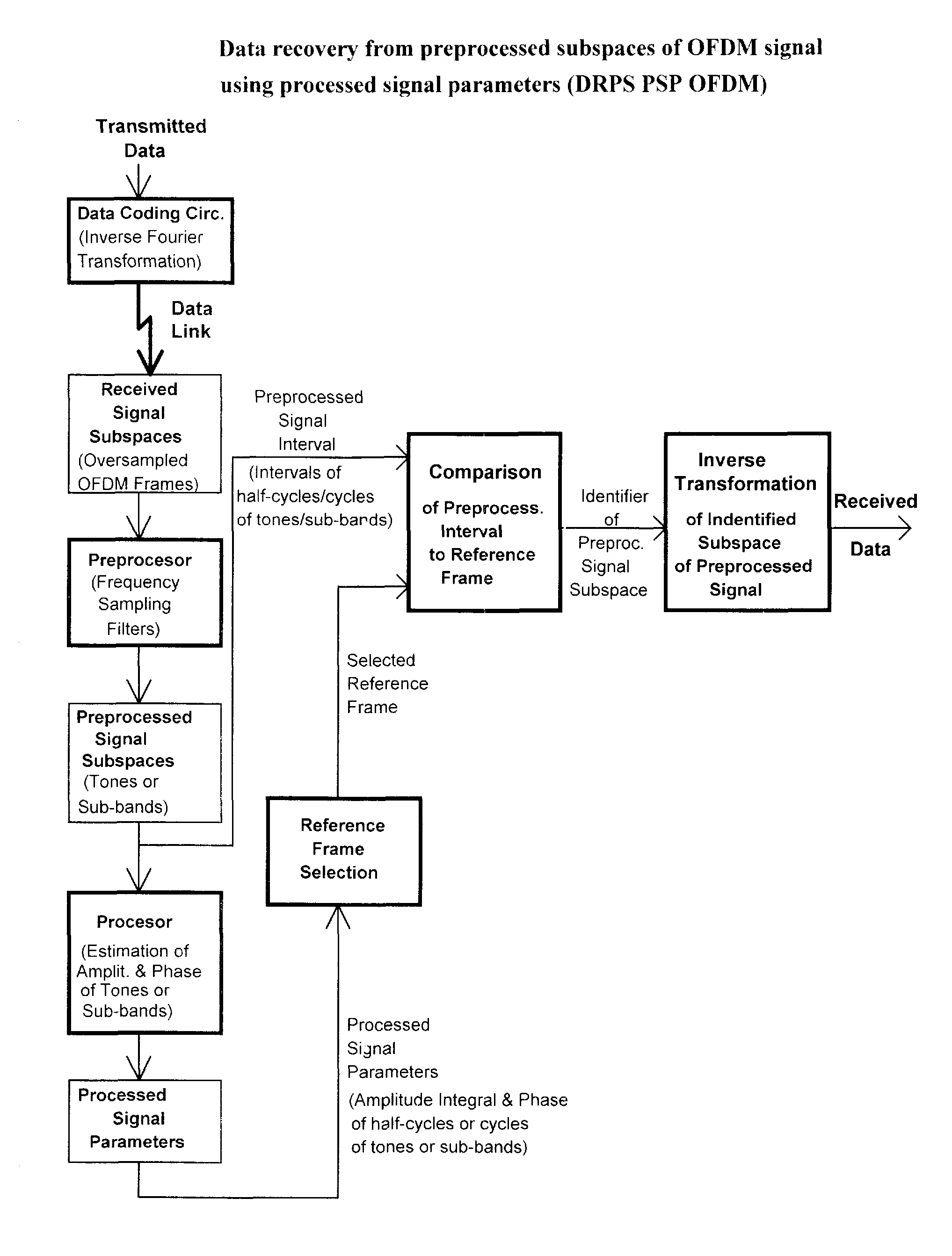
Such conventional synchronization solutions for OFDM receivers did not succeed in providing reliable and accurate recovery of a referencing frame providing time domain definition of phase and frequency of received OFDM composite frame.
OFDM composite signal has not been originally designed to carry distinctive edges enabling detection of composite frame boundaries, and conventional DFT / IDFT frequency domain processing is not well suited for any accurate detection of such boundaries occurring in time domain either.
Conventional DSP techniques and processors used are not equipped to perform real-time processing of OFDM signal needed to produce such referencing frame maintaining predictable accurate timing relation to the OFDM signal received.

Method used


Image

  • Inverse signal transformation
  • Inverse signal transformation
  • Inverse signal transformation

Examples


Embodiment Construction

[1054]1. Embodiments of NFIT

[1055]The Inverse Transformation Method (ITM) is introduced in FIG. 23 as including subsystems shown in blocks 1-7.

[1056]These subsystems enable an efficient low-power processing of high-speed oversampled data is enabled by implementing real-time processing units (RTPs) which use simplified algorithms based on variable coefficients.

[1057]These RTPs are controlled by a Programmable Control Unit (PCU) which performs a background processing. This background processing includes implementing adaptive non-linear algorithms which analyze received line signal and intermediate processing results, in order to define such coefficients and to download them to content addressed memories such as the Control Register Set for 129 Tone (mentioned further below as 129T_CRS occurring in FIG. 26, FIG. 28 and FIG. 29).

[1058]These memories are accessed by the RTPs implementing said ITM outlined in FIG. 23. These RTPs can be implemented as it is detailed below for 129 Tone of D...


PUM


Abstract

This application presents a direct data recovery from subspaces or parameters subranges of a received OFDM signal pre-identified as corresponding to specific data symbols, by applying inverse signal transformation (IST) reversing deterministic and random distortions introduced by a transmission channel. The direct data recovery can eliminate an intermediate recovery of signal transmitted originally from the received OFDM signal and reduce processing errors, power consumption and computing resources required by such intermediate recovery in conventional receivers.

Description

CROSS-REFERENCE TO RELATED APPLICATIONS[0001]This application is Continuation In Part of:[0002]U.S. non-provisional application Ser. No. 12 / 047,318, filed on 12 Mar. 2008, now U.S. Pat. No. 8,284,877, which is incorporated by reference herein as if fully set forth, wherein such U.S. Ser. No. 12 / 047,318 claims priority benefits of U.S. provisional application 60 / 894,433 filed on 12 Mar. 2007;[0003]U.S. non-provisional application Ser. No. 11 / 931,026, filed on Oct. 31, 2007, now U.S. Pat. No. 8,358,725, which is incorporated by reference herein as if fully set forth, wherein such Ser. No. 11 / 931,026 claims priority benefits and is Continuation In Part of PCT international application no. PCT / CA2006 / 001120, filed Jun. 27, 2006.BACKGROUND OF THE INVENTION[0004]1. Field of the Invention[0005]This application presents inverse signal transformation (IST) reversing transmission channel transfer function, in order to achieve a direct recovery of original data and synchronizing clock from rec...

Claims


Application Information

Patent Timeline
Patent Type & Authority Patents(United States)
IPC IPC(8): H04L25/03H04L27/26H03H17/04H03H17/02
CPCH03H17/04H04L27/2647H04L25/0398H03H17/0251H04L27/2657H04L27/2695
Inventor BOGDAN, JOHN W.
Owner BOGDAN JOHN W
Why Eureka
Try Eureka