Spine surgery device

a spine surgery and spine technology, applied in the field of spine surgery devices, can solve the problems of limiting the amount of disc material that can be safely removed, affecting the safety of patients, and affecting the recovery of patients, so as to reduce the effect of migration

Inactive Publication Date: 2015-07-14
AZADEH FARIN WALD M D INC A MEDICAL
View PDF107 Cites 17 Cited by
  • Summary
  • Abstract
  • Description
  • Claims
  • Application Information

AI Technical Summary

Problems solved by technology

Spine surgeons are now seeing many patients return post-fusion with symptoms limiting their professional, personal, and social functionality that stem from a fusion performed in the past without appropriate consideration for the biomechanical principle of sagittal balance and restoration of lumbar lordosis.
The traditional posterior approach is well-tolerated by patients but can restrict the amount of disc material that can be removed safely and more importantly restricts the size and type of currently available cage that can be placed through this small opening, an orifice limited by the degree of traction that can be placed on critical nerve roots or otherwise limited by the window of access to the disc space.
Current grafts available for insertion via a posterior approach are hampered by subphysiologic degrees of lordosis and endplate coverage, compared with anatomically appropriate lordotic grafts with larger endplate coverage.
Given currently available technology, marketed grafts and described techniques, these subpar grafts are inserted from a posterior trajectory and do not restore appropriate lumbar lordosis or sagittal balance.
Up to now, limited space afforded by a posterior approach because of proximity of critical nerve roots has seemingly and supposedly limited the size and type of graft that has been marketed as available for posterior insertion.
Anatomically and biomechanically, the posterior approach to discectomy and fusion, using currently available implants, is further limited in its ability to reestablish optimal lumbar lordosis and restore global sagittal balance (global sagittal imbalance is defined as a distance of greater than 50 mm from the C7 sagittal vertical axis and the S1 sagittal vertical axis), key biomechanical phenomena proven in the literature to be critical to successful patient outcomes.
However, the ALIF is somewhat limited in its employment because it requires access to the anterior part of the spine to be provided by a trained vascular or other qualified surgeon before the spine surgeon can perform discectomy and fusion (whereas the posterior approach does not require an approach surgeon).
The anterior approach can lead to life-threatening consequences, such as loss of limb and life-threatening hemorrhage, as well as retrograde ejaculation in men, impairing their fertility.
Finally, the anterior approach carries a risk of abdominal pseudohernia or true hernia.
These potential complications and hassles explain why most spine surgeons prefer the more practical posterior approach and use currently available grafts, but compromise with fusion rates, lordosis reestablishment and sagittal balance correction that is inferior to an anterior approach with a more biomechanically sound graft.
While there are some devices known in the art that are configured for posterior insertion while seeking increased disc and intervertebral height in excess of that traditionally achieved by grafts used in the past during the posterior approach, these devices each suffer from their own limitations and do not correct for the biomechanical shortcomings of current grafts as described above.

Method used


Image

  • Spine surgery device
  • Spine surgery device
  • Spine surgery device

Examples


examples

[0036]The following non-limiting examples are provided to further illustrate embodiments of the invention disclosed herein. It should be appreciated by those of skill in the art that the techniques disclosed in the examples that follow represent approaches that have been found to function well in the practice of the invention, and thus can be considered to constitute an example of a mode for its practice. However, those of skill in the art should, in light of the present disclosure, appreciate that many changes can be made in the specific embodiments that are disclosed and still obtain a like or similar result without departing from the spirit and scope of the invention.

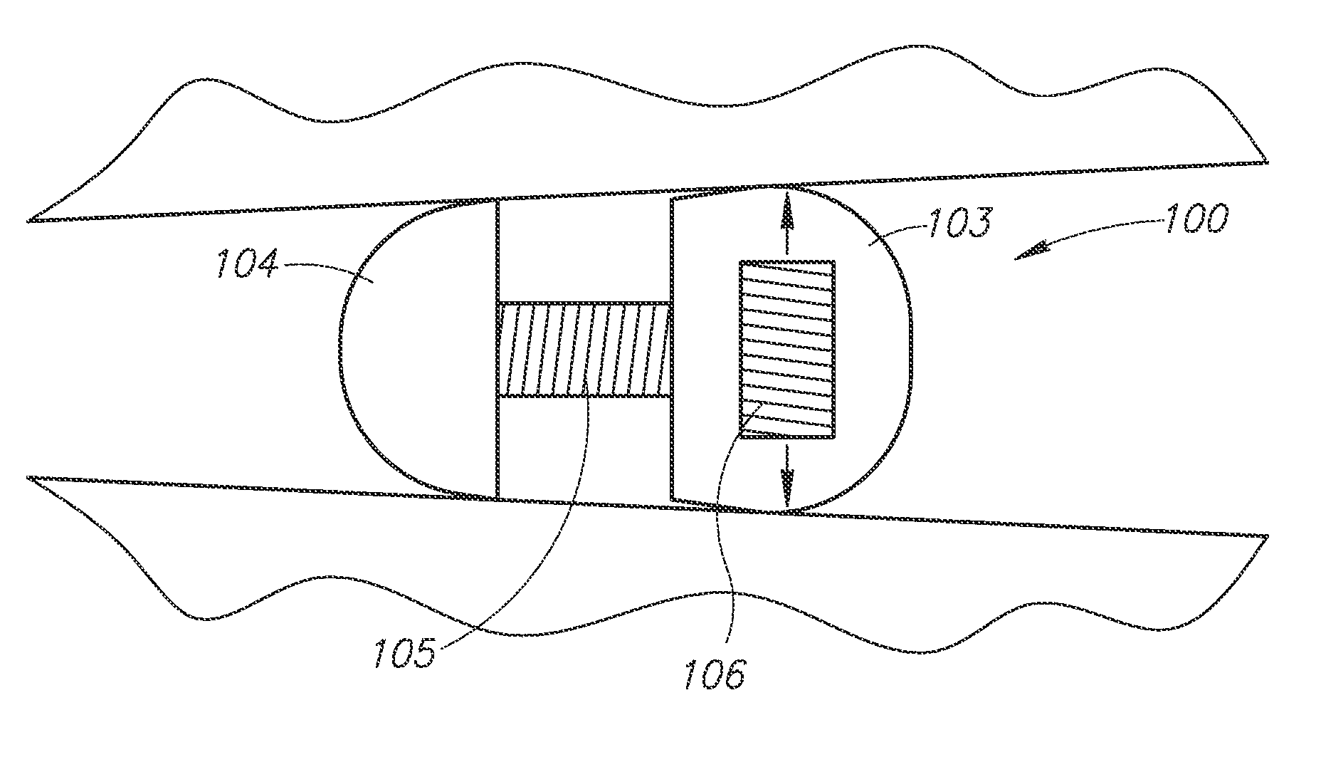
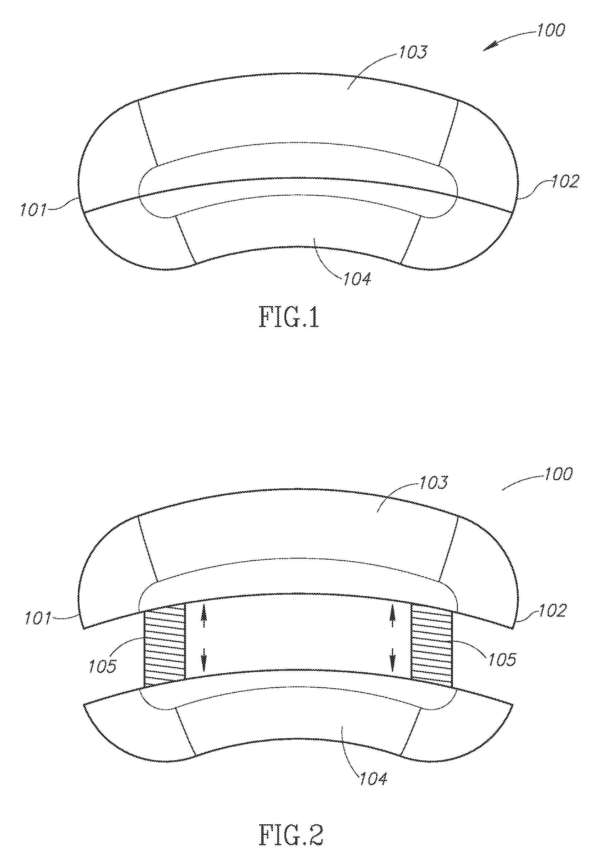
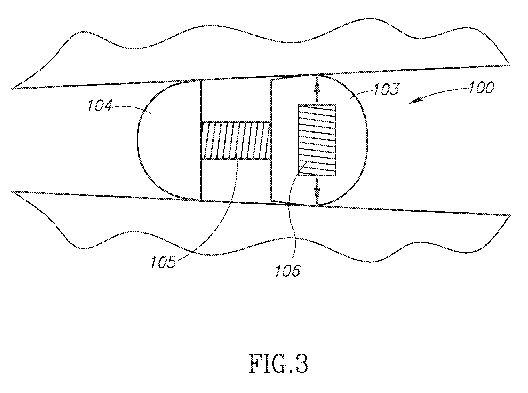
[0037]A device as illustrated in FIG. 1 is provided, along with a distractor tool as described herein and a disc removal tool as described herein. During a spine surgery procedure, following macroscopic discectomy, the distractor tool is inserted into the interbody space, and its pairs of blades are extended in the r...


PUM


Abstract

The invention relates to a device intended to replace or partially replace one or more vertebral bodies or intervertebral discs in the cervical, thoracic or lumbar spine, and includes methods for its use and deployment. The invention may be used to restore biomechanical parameters correlating with improved patient outcomes and also involves a method for a more effective discectomy or corpectomy prior to graft deployment.

Description

CROSS-REFERENCE TO RELATED APPLICATIONS[0001]This application is the National Phase of International Application PCT / US11 / 23502, filed Feb. 2, 2011, which designated the U.S. and that International Application was published under PCT Article 21(2) in English. This application also includes a claim of priority under 35 U.S.C. §119(e) to U.S. provisional patent application No. 61 / 300,580, filed Feb. 2, 2010.BACKGROUND OF THE INVENTION[0002]1. Field of the Invention[0003]The present invention is directed generally to a device intended to replace or partially replace a vertebral body or intervertebral disc in the cervical, thoracic or lumbar spine, as well as methods for its use and deployment.[0004]2. Description of the Related Art[0005]All publications cited herein are incorporated by reference in their entirety to the same extent as if each individual publication or patent application was specifically and individually indicated to be incorporated by reference. The following descripti...

Claims


Application Information

Patent Timeline
Patent Type & Authority Patents(United States)
IPC IPC(8): A61F2/44A61B17/02A61F2/30A61F2/28
CPCA61F2/4465A61F2/442A61B2017/0256A61F2/30907A61F2002/2817A61F2002/2835A61F2002/3055A61F2002/30405A61F2002/30448A61F2002/30484A61F2002/30556A61F2002/30579A61F2002/30841A61F2002/30914A61F2/30771A61F2002/30904
Inventor FARIN, AZADEH
Owner AZADEH FARIN WALD M D INC A MEDICAL
Why Eureka
Try Eureka