Inter-locking mechanism for lighting components and method thereof

a technology of interlocking mechanism and lighting components, which is applied in the direction of lighting and heating apparatus, semiconductor devices for light sources, lighting applications, etc., can solve the problems of increasing manufacturing costs, requiring maintenance of some sort, and ultimately the cost of the final product, so as to achieve tighter fit

Inactive Publication Date: 2015-07-14
SPECIALITY LIGHTING IND
View PDF2 Cites 0 Cited by
  • Summary
  • Abstract
  • Description
  • Claims
  • Application Information

AI Technical Summary

Benefits of technology

The patent describes a retention ring that holds a lighting component in place within a base. The retention ring slides over the lighting component and is secured in place by winged protrusions that engage with slots or ramps on the assembly component of the base. This creates a tighter fit, ensuring that the lighting component is securely attached to the base. The retention ring may be rotated using a tool attached to a socket wrench or similar device, which fits into the opening of the retention ring and engages with a stopper to secure the lighting component. This design provides a more secure and efficient attachment than manual rotation.

Problems solved by technology

As such, assembly of the lighting components in a factory or warehouse can be extremely labor intensive and time consuming, which increases manufacturing costs, and ultimately the cost of the final product.
Therefore, a lot of time and labor are expended to assemble the light fixtures.
In addition, after the lighting fixture has been assembled and installed in the field, it will eventually require maintenance of some sort, such as the replacement of a bulb or another faulty component.
As with the assembly stage, this can be a labor intensive process.
Because the lighting fixture is already installed in either a wall or a ceiling, it can be painstaking procedure to remove each screw attaching the collar to the base in order to access the LED or light engine module, thereby increasing maintenance costs.
In addition, because the screws are very small, at least one screw could easily be lost, thereby negatively affecting the collar's hold of the LED or light engine module against the base after the faulty component is replaced and the fixture is reassembled.
This in turn will decrease the contact between the LED or light engine module and the base, and therefore reduce the efficiency of the LED or light engine.

Method used


Image

  • Inter-locking mechanism for lighting components and method thereof
  • Inter-locking mechanism for lighting components and method thereof
  • Inter-locking mechanism for lighting components and method thereof

Examples


Embodiment Construction

[0036]In the following detailed description, numerous specific details are set forth in order to provide a thorough understanding of embodiments or other examples described herein. In some instances, well-known methods, procedures, components and circuits have not been described in detail, so as to not obscure the following description.

[0037]Further, the examples disclosed are for exemplary purposes only and other examples may be employed in lieu of, or in combination with, the examples disclosed. It should also be noted the examples presented herein should not be construed as limiting of the scope of embodiments of the present disclosure, as other equally effective examples are possible and likely.

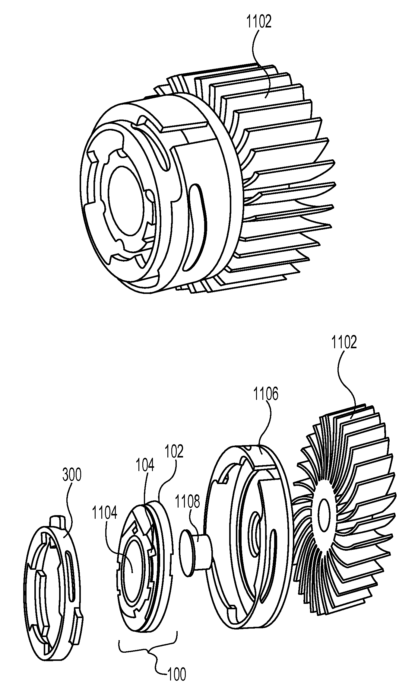
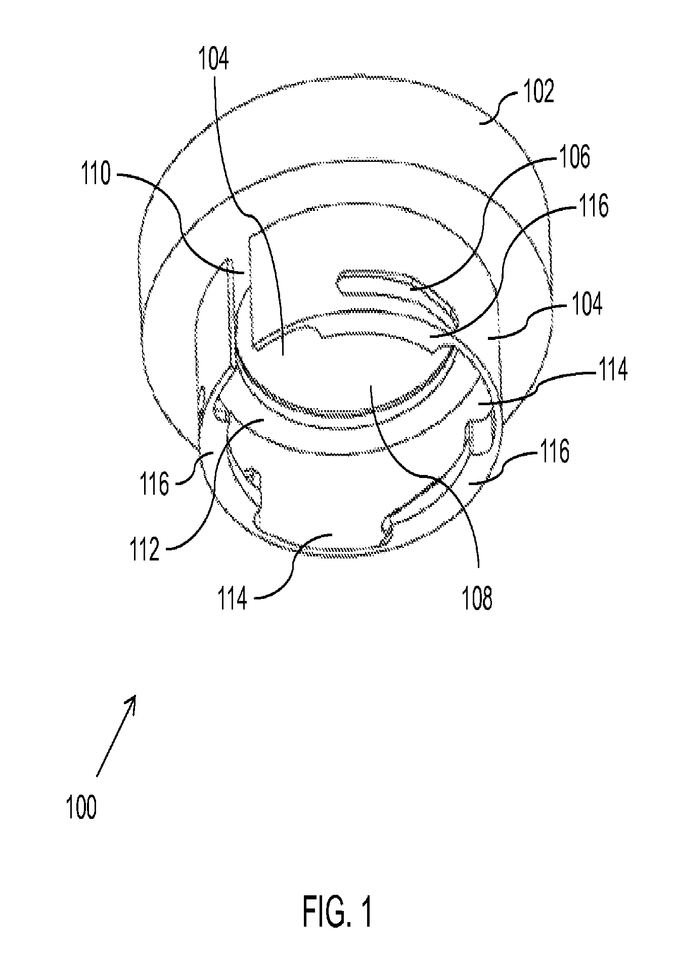
[0038]Embodiments of the present invention provide a locking mechanism for securing lighting components to each other, such as light-emitting diode (LED) module or any light engine may be connected to a heat sink. Herein this disclosure, the light engine may be referred to any solid state...


PUM


Abstract

Embodiments of the disclosure provide a locking mechanism for securing lighting components to each other, particularly a light-emitting diode (LED) or light engine to a heat sink. The locking mechanism comprises: a base component and a retention ring. The base component comprises: a mounting component comprising a lighting component compartment; and an assembly component comprising: an opening through which wires pass, at least two slots or ramps, and at least one bottom ledge. The retention ring further comprises: at least two winged protrusions, each to engage with a slot of the assembly component, at least one top and bottom ledge, and at least one slot.

Description

CROSS-REFERENCE TO RELATED APPLICATIONS[0001]The present application claims the benefit under 35 U.S.C. §120 of U.S. patent application Ser. No. 13 / 774,912, which was filed on Feb. 22, 2013 which in turn is based upon and claims the benefit of U.S. Provisional Application Ser. No. 61 / 601,918 filed Feb. 22, 2012, entitled “LOCKING MECHANISM FOR LIGHTING COMPONENTS,” which is incorporated herein by reference in its entirety.BACKGROUND[0002]1. Field of the Invention[0003]Embodiments of the present invention generally relate to a locking mechanism. More specifically, the present invention relates to a locking mechanism for securing lighting components, such as light-emitting diodes (LED) or light engine, without necessarily using screws or other fasteners, and a method of using the same.[0004]2. Description of Related Art[0005]Lighting fixtures have many components and parts, in addition to the lamp or lighting module. This may include, for example, a housing, a ballast, a reflector, or...

Claims


Application Information

Patent Timeline
Patent Type & Authority Patents(United States)
IPC IPC(8): F21V17/18F21V17/14F21V19/00F21V29/76F21V29/74F21W131/402F21Y101/02
CPCF21V17/18F21V17/14F21V19/003F21V29/74F21V29/76F21W2131/402F21Y2101/02F21Y2115/10
Inventor SALOMON, BEN
Owner SPECIALITY LIGHTING IND
Why Eureka
Try Eureka