Power generation and control system

a power generation and control system technology, applied in the direction of magnetism bodies, emergency power supply arrangements, cores/yokes, etc., to achieve the effect of easy installation and easy connection of power generation devices

Active Publication Date: 2015-07-14
NETHERY III STANTON KEE
View PDF16 Cites 1 Cited by
  • Summary
  • Abstract
  • Description
  • Claims
  • Application Information

AI Technical Summary

Benefits of technology

[0011]The present invention is directed to a system that prevents power from flowing back into a power grid during a power outage and prevents end-user installable power generation systems from operating on a power circuit that does not have this protection. As such, the invention provides all the necessary components for power generation systems so that they can be purchased and installed by anyone without the added expense of engineering documents, permits or qualified installers such as electricians.
[0012]In a preferred embodiment of the invention, a power generation and control system is easily installed in a consumer household, a business or an end-user establishment; generates power; and prevents power from flowing to a power line from a consumer circuit during a power outage. The end-user electrical system power generation and control system includes a main power flow controller for controlling a flow of power between the power grid and the consumer circuit. The controller includes an input adapted to be connected to the power grid and an output connected to the consumer circuit. A power sensor associated with the controller senses if power is in the power line or if there is a flow of power between the power grid and the consumer circuit. A power control switch located between the power sensor and the output interrupts the flow of power between the power line and the consumer circuit when the power sensor senses a power outage in the power line and there is power being generated in the consumer circuit that is flowing to the power grid. In another preferred embodiment, a communications transceiver is adapted to transmit a permission or enabling signal across the consumer circuit. Alternatively, the communications transceiver is adapted to transmit the signal wirelessly or through separate dedicated wires. The power generation controller includes a power generation transceiver adapted to receive the signal generated by the power line communications transceiver. The power generation controller ensures that the power generation device will only operate when it receives permission from the power flow controls through the consumer circuit connecting the controller and generators. This ensures that the controller is upstream of and controls the specific consumer power circuit of the generator. Once the power generator controller is installed, anyone can easily connect the power generation device without hiring a professional electrician knowing that repairmen will be safe in the event of a power outage.
[0013]In another preferred embodiment, a power storage unit is in communication with the power generation device and adapted to store power generated by the power generation device. The power storage unit provides a relatively low voltage power signal to power the power flow controller during an outage and can provide power to start the power generation device. In another preferred embodiment, when the power generation device is not providing power, the power generation device can be activated to supply relatively low voltage power to the power flow controller during a power outage and provide power to activate the power flow controller so that it can isolate the consumer circuit from the power circuit and grant permission to the power generator to supply power to the consumer circuit. This handles the situation when all power is off and the power generator is desired to be on but cannot receive permission to do so from the power controller because the power controller has no power to operate.
[0015]The system is installed in a consumer household or a business establishment by installing the power generation control system and user establishment generating a permission signal to indicate the presence of the control system; and enabling the power generation device to provide power only when the permission signal is provided by the control system. Preferably, this method also includes monitoring the power line to determine whether there is power on the power line and preventing power from flowing from the consumer circuit to the power line when there is no power on the power line, while allowing power to flow from the consumer circuit to the power line when there is power on the power line. Preferably, the method also includes supplying power to the control system with a relatively low voltage signal during a power outage. The method allows installation of the power generation device without requiring an electrician to modify the consumer circuit.

Problems solved by technology

This handles the situation when all power is off and the power generator is desired to be on but cannot receive permission to do so from the power controller because the power controller has no power to operate.

Method used


Image

  • Power generation and control system
  • Power generation and control system
  • Power generation and control system

Examples


Embodiment Construction

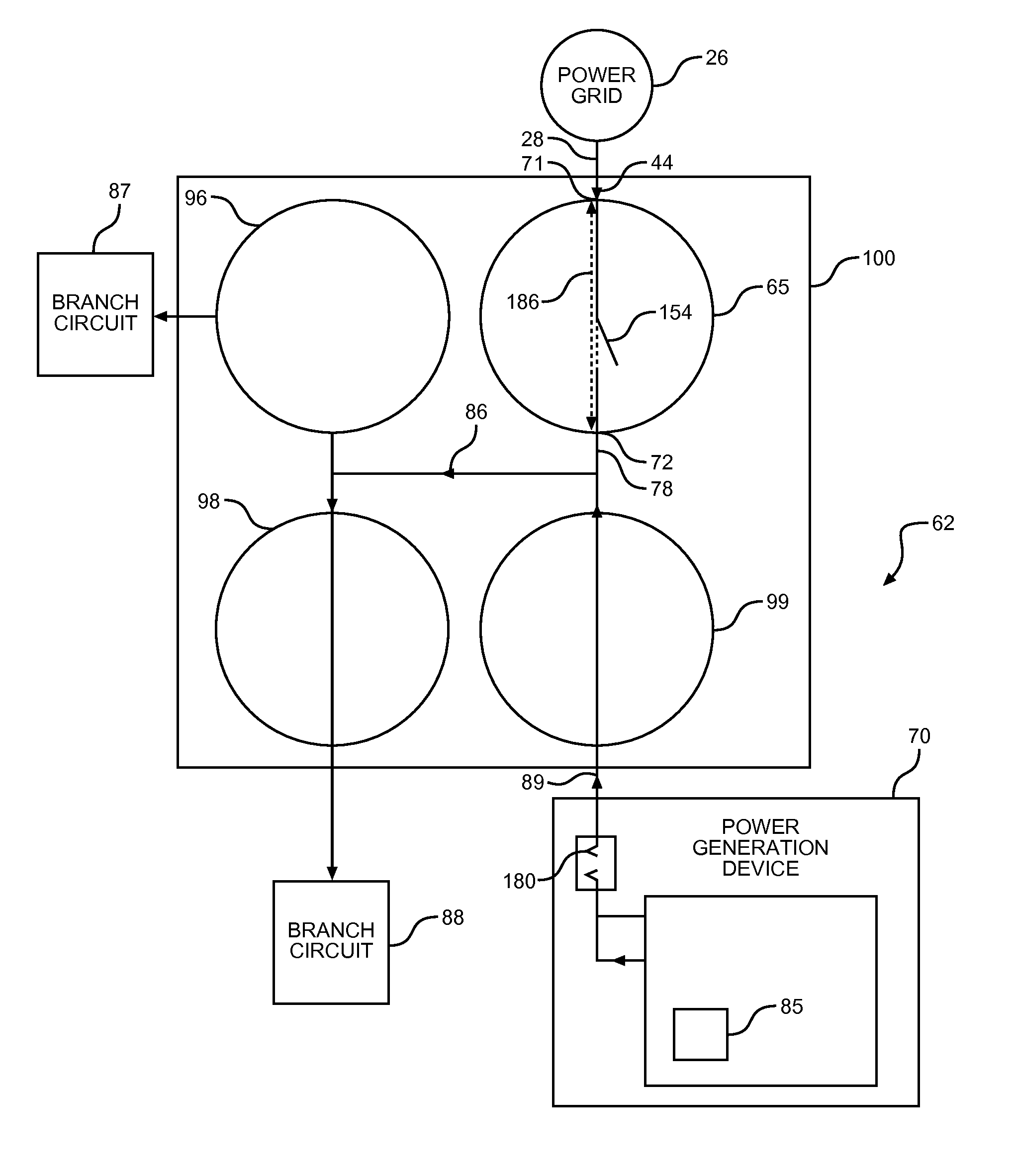
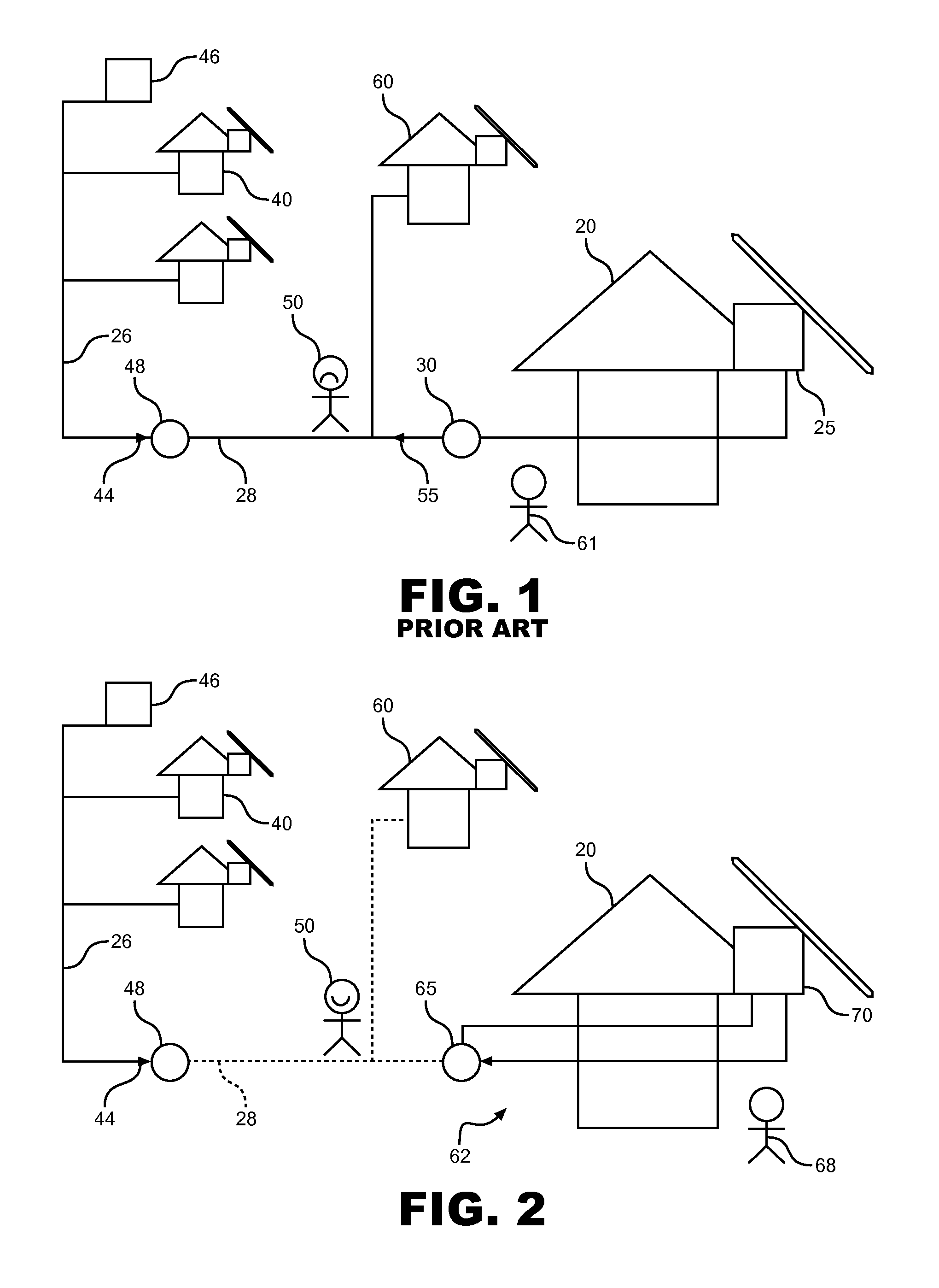
[0023]With initial reference to FIGS. 1-3, a consumer household, business or other end-user establishment 20 is provided with a power generation and control system 62 in accordance with a preferred embodiment of the invention. Power generation and control system 62 is shown in communication with power line 28, which receives power 44 through switch 48 from power grid 26. A main power flow controller 65 of the present invention, provided between an end-user power generation device 70 and power line 28, prevents any undesirable power feedback (corresponding to power feedback 55 shown in FIG. 1) from flowing to power line 28 from power generation device 70. As more fully explained below, power generation device 70 is installable by an end-user 68 and does not require an electrician 61 to install.

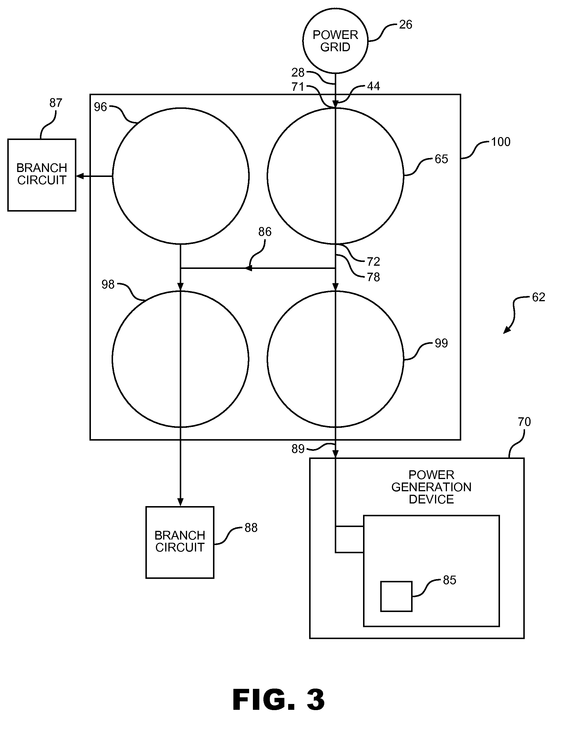
[0024]An overview of power generation and control system 62 of the present invention is depicted in FIG. 3. Power generation and control system 62 includes power generation device 70 and power ...


PUM


Abstract

A power generation and control system is easily installed in a consumer household, a business, or an end-user establishment for generating power and preventing power from flowing to a power grid from a consumer circuit during a power outage. A communications transceiver is adapted to transmit a permission signal for allowing power generation only after the control system has been installed. The control system can be adapted to replace an existing circuit breaker in a household circuit breaker box and prevents power from traveling from consumer power generators to the grid during a power outage. In the same manner that end-users can add appliances to existing circuits, end-users can easily add additional power generation devices without hiring a professional electrician and without worrying about causing harm to utility workman during power outages.

Description

CROSS-REFERENCE TO RELATED APPLICATIONS[0001]The present invention claims the benefit of U.S. Provisional Patent Application Ser. No. 61 / 136,342 entitled “Power Generation and Control System” filed Aug. 28, 2008.BACKGROUND OF THE INVENTION[0002]1. Field of the Invention[0003]The present invention pertains to the art of power generation and power generation control systems and, more particularly, to power generation and power generation control systems that can be easily installed in a consumer household, a business or other end-user establishment.[0004]2. Discussion of the Prior Art[0005]In general, large centralized power grids or networks are utilized to provide power to multitudes of consumer households, businesses and other end-users. Distribution of electric power from power plants to households and businesses is conducted over a network of utility lines connected to each residence and business. A standard consumer household, business or end user establishment has a consumer ci...

Claims


Application Information

Patent Timeline
Patent Type & Authority Patents(United States)
IPC IPC(8): H02J9/00H02H3/00H02H11/00
CPCH02H3/003H02H11/008Y02B10/14Y02E10/56Y02B10/10H02J3/38H02J3/388H02J11/00
Inventor NETHERY, III, STANTON KEE
Owner NETHERY III STANTON KEE
Why Eureka
Try Eureka