

Magnetic microstructures for magnetic resonance imaging
a magnetic resonance imaging and microstructure technology, applied in the field of magnetic resonance imaging contrast agents and magnetic resonance imaging methods, can solve the problem that optically based labels can only probe so far beneath most surfaces
- Summary
- Abstract
- Description
- Claims
- Application Information
AI Technical Summary
Problems solved by technology
Method used
Image

Examples
example 1
Assessment of Saturation of Dual-Disk Magnetic Resonance Structures
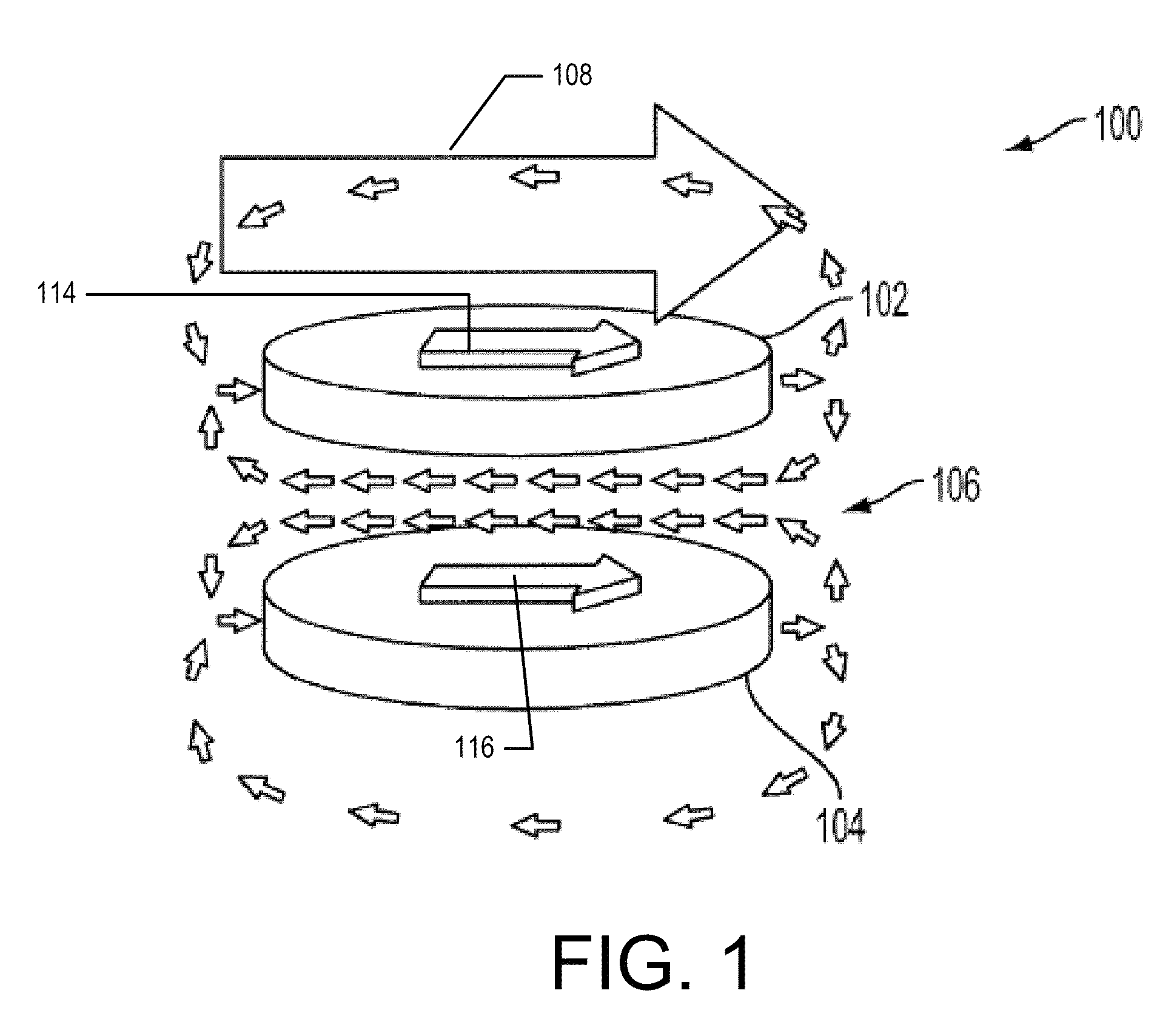
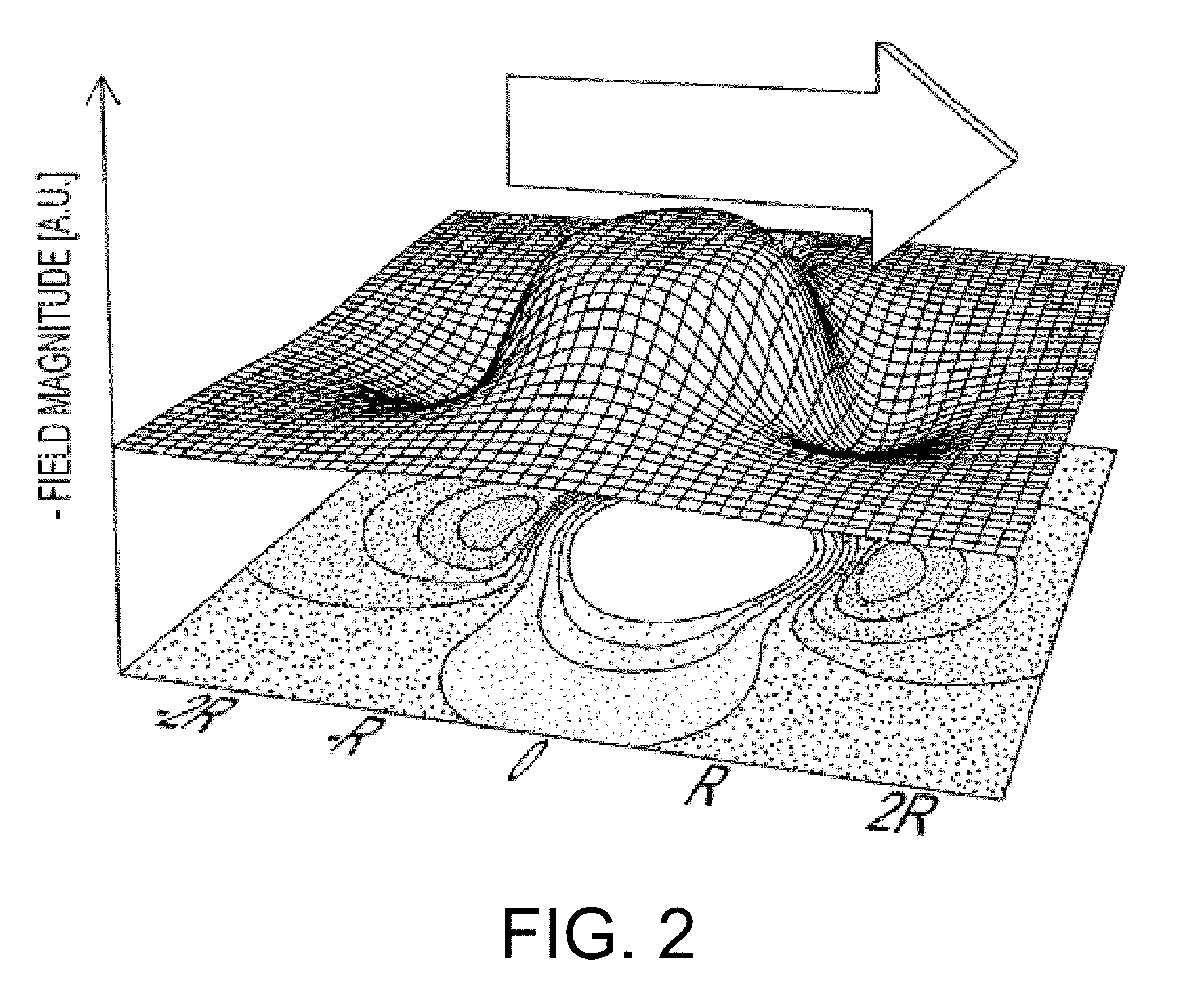
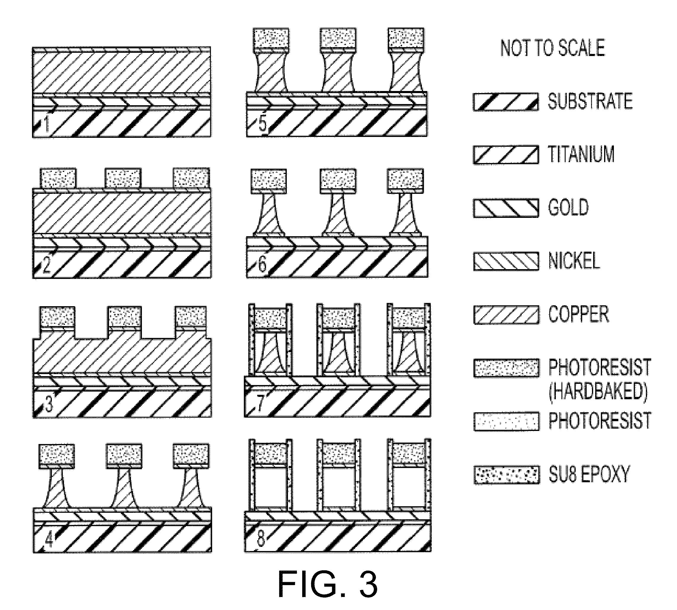
[0339]To assess the effect of the magnitude of applied magnetic field on the magnitude of the induced magnetic field in the reserved volume of a magnetic resonance structure, the following experiment was conducted. A 13 mm×13 mm grid of immobilized dual-disk magnetic resonance structures was tested using an alternating gradient magnetometer to assess the magnitude of the magnetic field induced within the reserved volumes as a function of the magnitude of the applied magnetic field, as well as the hysteresis of the induced magnetic field during a full alternating gradient cycle. Each dual-disk magnetic resonance structure in the 13 mm×13 mm grid was formed on a 15 mm×15 mm diced Pyrex substrate using microfabrication techniques. Each disk in a dual-disk magnetic resonance structure was a pure nickel disks having a disk radius of about 2.5 μm, a thickness of about 50 nm, and a disk separation distance of about 2 μm. Th...
example 2
Multi-Spectral Imaging Using Dual-Disk Magnetic Resonance Structures
[0343]To assess the effectiveness of multispectral imaging using magnetic resonance structures in a magnetic resonance scanning device, the following experiment was conducted. A grid of immobilized nickel dual-disk magnetic resonance structures were fabricated in a manner similar to those described in Example 1. The disks in each dual-disk magnetic resonance structure in this experiment had a diameter of about 1.25 mm and a separation of about 500 mm between the disks. Inter-particle spacings (center-to-center) were typically 3 to 4 times the particle diameter to minimize the influence from the induced far-field magnetic fields of neighboring particles on the chemical shifting of each individual magnetic resonance structure in the grid. Subgroups of the dual-disk magnetic resonance structures had disk thicknesses of 4, 6, and 8 μm respectively in order to vary the frequency shift induced by each respective subgroup....
example 3
Frequency-Shifting of Deuterium Proton Signals by Dual-Disk Magnetic Resonance Structures
[0348]To determine the effectiveness of the frequency-shifting of protons other than water protons, the following experiment was conducted. A grid of dual-disk magnetic resonance structures similar to those described in Example 1 were submerged in deuterium oxide (D2O) and imaged in a manner similar that described in Example 2. In this experiment, the disks in the dual-disk magnetic resonant structures had a diameter of about 25 μm, a disk thickness of about 0.5 μm, and a separation distance of about 10 μm between the disks. A grid of dual-disk magnetic resonance structures was constructed similar to those described in Example 1.
[0349]An individual pyrex chip was placed in a custom-made holder and filled with a layer of deuterium oxide (D2O) to a thickness of about 150 μm, in order to submerge the particles and provide an additional layer of deuterium oxide (D2O) well above the extent of any app...
PUM
 Abstract
Description
Claims
Application Information