Optical system for following ocular movements and associated support device

a technology of optical system and ocular movement, which is applied in the field of optical system for tracking ocular movement, can solve the problems of introducing optical distortion, bulky system, and difficult to utilize in a portable manner, and achieves the effects of reducing the reflection present on the individual's eyes, reducing the optical distortion of acquired images, and facilitating detection and analysis

Active Publication Date: 2015-07-28
SURICOG
View PDF31 Cites 0 Cited by
  • Summary
  • Abstract
  • Description
  • Claims
  • Application Information

AI Technical Summary

Benefits of technology

[0031]According to a particular feature, said second mirrors of the two optical assemblies are contiguous. This arrangement offers an optimization of the detection surface constituted by the acquisition module. In fact, the acquired image in this case comprises the two acquired non-contiguous portions of the face, in a contiguous manner. Thus no detection pixel is lost. This of course results in optimum definition of the acquired image portions for each eye.
[0032]In particular, the contiguous edge of said second mirrors is placed substantially in the optical axis of the image-acquisition module. In this way, the detection surface is equally divided for acquisition of the image portions for both eyes. Moreover, this configuration minimizes the optical distortions of the acquired images.
[0033]In an embodiment, the optical paths comprise output optical paths striking said image-acquisition module, which are parallel to each other and to the optical axis of the image-acquisition module.
[0034]In an embodiment, the optical system comprises, at the level of two input zones of the optical means of transmission to be placed opposite each eye, an optical wavelength filteri

Problems solved by technology

In this case, the presence of the two cameras makes these systems bulky and therefore difficult to utilize in a portable manner.
This distance presents a few drawbacks, and in particular a lower definition (in pixels) allocated to each eye in the image and the introduction of optical distortions.
Analysis of the images in order to deduce ocular movements from them therefore proves more difficult.
In all of these optical systems, the presence of a semi-reflective mirror in the patient's field of view also constitutes a significant drawback, for at least two reasons.
On the other hand, the

Method used


Image

  • Optical system for following ocular movements and associated support device
  • Optical system for following ocular movements and associated support device
  • Optical system for following ocular movements and associated support device

Examples


Embodiment Construction

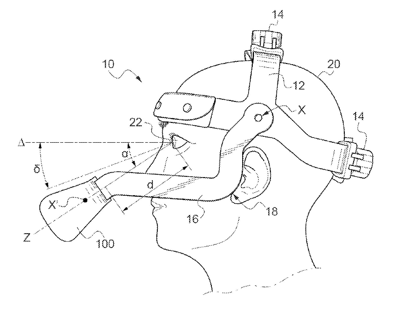
[0049]With reference to FIG. 1, a helmet-type support 10 for tracking the ocular movements of an individual comprises a helmet structure 12 provided in order to be adjusted to the head of an individual 20, for example using elastic means (holding elastic strap passing around the head) or mechanical adjustment means 14.

[0050]The helmet 10 also comprises two attachment arms 16 on either side of the individual's face, mounted mobile in rotation about the horizontal axis X relative to the structure 12.

[0051]The attachment arms 16 are bent and extend diagonally from the points of rotation situated at the height of the individual's temporal areas towards the lower part of the face, firstly by a substantially vertical section, then by a horizontal section. The bend 18 makes it possible, as the figure shows, to free the individual's side field of view.

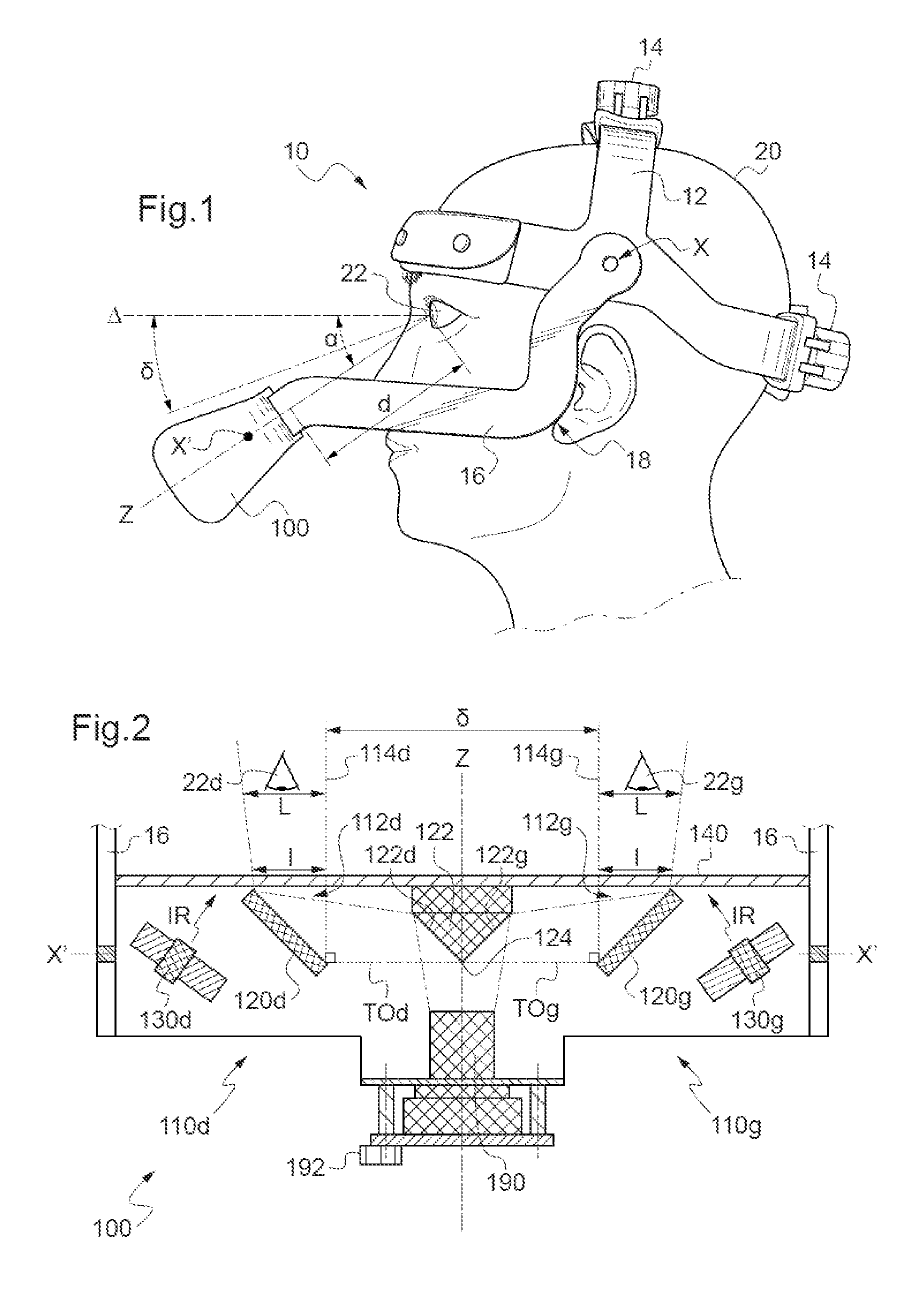
[0052]At the end of the two attachment arms there is arranged, in an articulated manner about the horizontal axis X′, an optical system 100 f...


PUM


Abstract

An optical system (100) for following ocular movements of an individual includes: an acquisition module (190) designed so as to acquire an image (Im) of the two eyes (22, 22d, 22g) of the individual, an optical element of transmission (110d, 110g), to the acquisition module, of two images (lm_d, lm_g) of respectively each eye which together correspond to a discontinuous region (24d, 24g) of the face, by multiple reflections along two optical routes (TOd, TOg) devoid of any semireflecting mirror. The optical routes further include optical input paths (114d, 114g) opposite respectively each eye, which are parallel to one another and to an optical axis (Z) of the acquisition module, and the optical element of transmission is configured so as to bring the two images closer together so that the acquisition module acquires the two images simultaneously.

Description

BACKGROUND OF THE INVENTION[0001]The present invention relates to an optical system for tracking ocular movements of an individual and an associated support-type device worn on the head like a helmet.DESCRIPTION OF THE RELATED ART[0002]The tracking of ocular movements takes place in numerous applications, medical as well as technological or marketing.[0003]For example, eye-movement analysis constitutes an aid to medical diagnosis, in particular in the diagnosis of neurological and psychiatric diseases such as neurodegenerative diseases including parkinsonian syndromes.[0004]This analysis also makes it possible to deepen understanding in research fields such as visual exploration, visual strategy or the exploration of pathologies.[0005]Another field of application is the detection of ocular movements in order to control electronic systems, such as for example the control of a computer pointer or of a high resolution display, by eye gaze.[0006]Conventional optical systems for tracking...

Claims


Application Information

Patent Timeline
IPC IPC(8): A61B3/14A61B5/00A61B3/113A61B3/10
CPCA61B3/113A61B5/6803
Inventor BERNERT, FREDERICMAILLARD, MICKAELKINKINGNEHUN, SERGE
Owner SURICOG
Why Eureka
Try Eureka