Drive assembly for a clutch unit and removable transmission equipped with said assembly

a technology of drive assembly and clutch unit, which is applied in the direction of fluid actuated clutches, non-mechanical actuated clutches, gearing elements, etc., can solve the problems of long machining time and high cost, and achieve the effect of low cost, simple and particularly functional manner

Inactive Publication Date: 2015-08-04
DANA ITAL SPA
View PDF8 Cites 0 Cited by
  • Summary
  • Abstract
  • Description
  • Claims
  • Application Information

AI Technical Summary

Benefits of technology

[0010]An object of the present invention is to provide a drive assembly for a clutch unit and a removable transmission equipped with this assembly which are able to overcome the abovementioned drawbacks of the prior art in an extremely simple, low-cost and particularly functional manner.
[0011]Another object is to provide a drive assembly for a clutch unit and a removable transmission equipped with this assembly which does not require the presence of any anti-rotational element in order to avoid any risk of seizing of the pusher on the shaft.

Problems solved by technology

Both the known solutions described have drawbacks such as the high costs and long machining time.

Method used


Image

  • Drive assembly for a clutch unit and removable transmission equipped with said assembly
  • Drive assembly for a clutch unit and removable transmission equipped with said assembly
  • Drive assembly for a clutch unit and removable transmission equipped with said assembly

Examples


Embodiment Construction

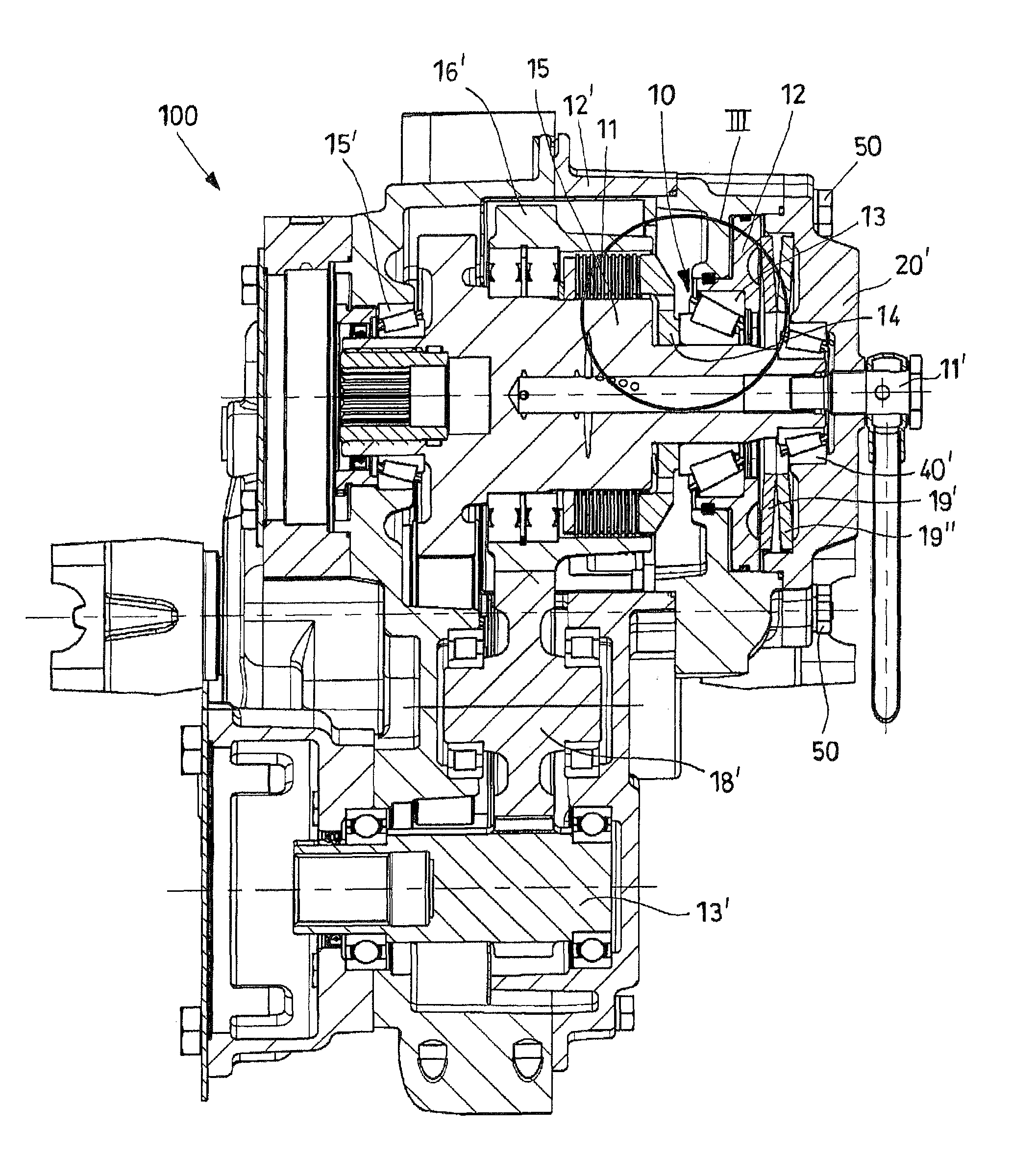
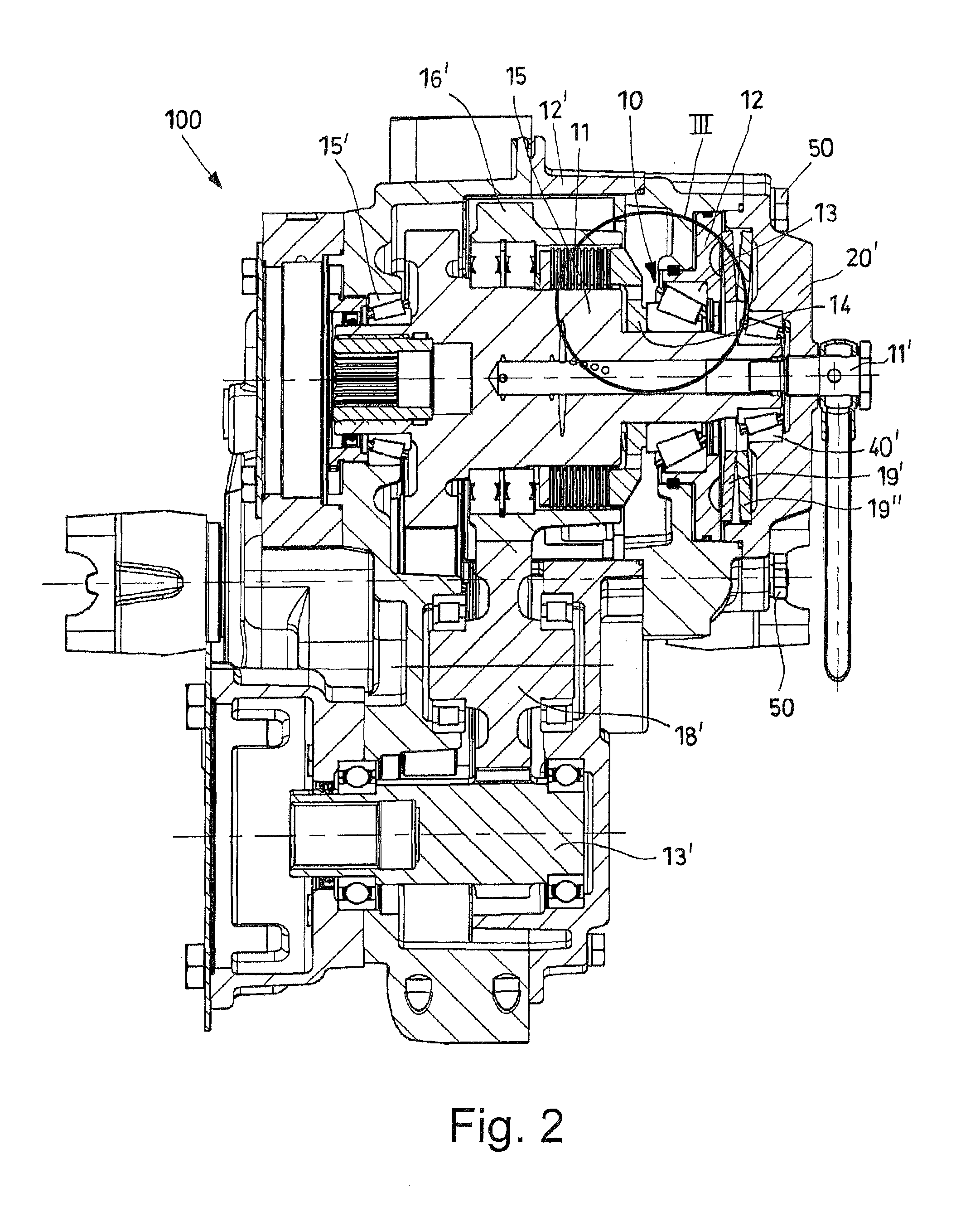
[0018]With reference to the figures, 10 denotes an example of embodiment of a drive assembly for a clutch unit according to the present invention and 100 denotes a removable transmission equipped with said assembly. This assembly 10, which can be seen in the assembled condition in FIG. 3 and in an exploded view in FIG. 4, comprises an actuating piston 12 for generating a thrust for engagement of the clutch, a bearing 13 for transferring the engagement thrust, and a pusher 14 for discharging the thrust onto the clutch unit 11. The actuating piston 12, the bearing 13 and the pusher 14 are assembled in succession on a transmission shaft 15 carrying the clutch unit 11.

[0019]A chamber 18A is envisaged for supplying a fluid under pressure for generating a disengagement thrust acting on the actuating piston 12 and at least one preloaded spring 19′, 19″, or equivalent means, acting on the actuating piston 12 so as to push it towards the clutch unit 11.

[0020]In particular, as shown in FIG. 3...


PUM


Abstract

A drive assembly having an actuating piston for generating a thrust for engagement of a clutch unit. The assembly also has a bearing for transferring the engagement thrust and a pusher for discharging the engagement thrust onto the clutch unit. The actuating piston, the bearing and the pusher are assembled in succession on a transmission shaft carrying the clutch unit. A chamber is provided for supplying a fluid under pressure for generating a disengagement thrust acting on the actuating piston. At least one preloaded spring is provided that acts on the actuating piston so as to push it towards the clutch unit. The bearing for transferring the thrust is mounted with play directly on the transmission shaft. The pusher being disk-shaped and comprising a first face in lateral contact with the bearing and a second face in lateral contact with the clutch unit.

Description

BACKGROUND OF THE INVENTION[0001]The present invention relates to a drive assembly for a clutch unit and to a removable transmission equipped with said assembly.[0002]FIG. 1 shows in schematic form a drive assembly for a clutch unit A according to the existing prior art.[0003]These assemblies comprise an actuating piston D for generating an engagement thrust, a bearing C for transferring the thrust, and a pusher E for discharging the thrust onto the clutch A.[0004]As shown, the actuating piston D, the bearing C and the pusher E are assembled in succession on a transmission shaft B carrying the clutch unit A.[0005]At least one preloaded spring or equivalent means acting on the actuating piston D so as to push it towards the clutch unit A is provided.[0006]In order to cause separation of the clutch, the presence of a chamber H supplying a fluid under pressure for generating a disengagement thrust acting on the actuating piston D is envisaged.[0007]An analysis of said prior art shows t...

Claims


Application Information

Patent Timeline
Patent Type & Authority Patents(United States)
IPC IPC(8): F16D25/08F16D25/06F16H63/30
CPCF16D25/083F16D25/06F16H63/3026F16H2063/303
Inventor PONTANARI, MARCO
Owner DANA ITAL SPA
Why Eureka
Try Eureka