Master brake cylinder, braking system

a brake system and master technology, applied in the direction of braking systems, vehicle sub-unit features, transportation and packaging, etc., can solve the problems of increasing production costs, difficult installation, mechanical limitation of the maximum relaxation of the spring element, etc., and achieve the effect of simple and low-cost manner

Active Publication Date: 2021-08-10
ROBERT BOSCH GMBH
View PDF14 Cites 0 Cited by
  • Summary
  • Abstract
  • Description
  • Claims
  • Application Information

AI Technical Summary

Benefits of technology

[0007]The master brake cylinder according to the present invention has the advantage that the damper is realized in a particularly simple and low-cost manner, and can be realized even when the master brake cylinder is realized as a tandem cylinder. Here, the constructive space required for the master brake cylinder is not expanded, or is expanded only slightly. According to the present invention, this is achieved in that the lateral wall opening is provided with an elastically deformable sealing ring whose inner side is fastened on the hydraulic piston, and whose outer side is preloaded against the hydraulic cylinder by its inherent elasticity and is shaped in such a way that when the hydraulic piston is displaced in the direction of actuation it detaches from the hydraulic cylinder, and when the hydraulic cylinder is displaced in the relief direction it bears on the hydraulic cylinder. The sealing ring thus acts as a check valve that opens when the hydraulic piston moves in the direction of actuation and that closes when there is a movement in the opposite direction. In this way, with simple means it is achieved that the movement of the hydraulic piston in the relief direction is dampened and in the direction of actuation is not impaired. In this way, the user is given the pedal feeling of a conventional brake system having a vacuum brake booster, even if the brake system has for example an electromechanical or electrohydraulic brake booster instead of a vacuum brake booster. In addition, due to the elastically deformable sealing ring that is fastened on the hydraulic piston and is thus movable with the hydraulic piston, an additional sleeve is no longer required and a compact realization of the master brake cylinder is possible.
[0008]According to a preferred specific embodiment of the present invention, it is provided that the sealing ring has a U-shaped or V-shaped cross-section. Through the U-shape or V-shape, the sealing ring is given a simple shape in order to form the check valve. The cross-section of the sealing ring is then realized such that the inner limb is connected to the hydraulic piston and the outer limb is oriented toward the hydraulic cylinder, or toward the inner wall of the hydraulic cylinder, the closed side of the sealing ring pointing in the direction of actuation and the open side pointing in the direction of relief, so that when the piston is moved in the direction of relief the fluid pressing against the sealing ring further expands the sealing ring and as a result reinforces the radial seal between the sealing ring and the inner wall of the hydraulic cylinder. In this way, a damping chamber between the sealing ring, hydraulic piston, and the hydraulic cylinder is formed, or closed, when the hydraulic piston moves in the relief direction.
[0009]Preferably, the sealing ring is fastened on the hydraulic piston before the first lateral wall opening, seen in the direction of actuation. Thus, if the piston is moved in the direction of actuation, or the user / driver depresses the brake pedal, the sealing ring is situated before the lateral wall opening. The lateral wall opening thus opens into the damping chamber. If the actuating piston is moved in the relief direction, the fluid held in the damping chamber can thus move through the lateral wall opening into the inner chamber of the hydraulic piston and thus escape from the damping chamber. In this way, the cross-section of the lateral wall opening determines the damping effect of the damping chamber.

Problems solved by technology

If a tie is allocated to the spring element, this tie mechanically limits the maximum relaxation of the spring element when the hydraulic piston is relieved by the driver.
However, the provision of the damping chamber requires additional constructive space, and, in particular given realization of the master brake cylinder as a tandem cylinder, the realization of the damping chamber requires an additional sleeve that makes installation more difficult and increases the production costs.

Method used


Image

  • Master brake cylinder, braking system
  • Master brake cylinder, braking system

Examples


Embodiment Construction

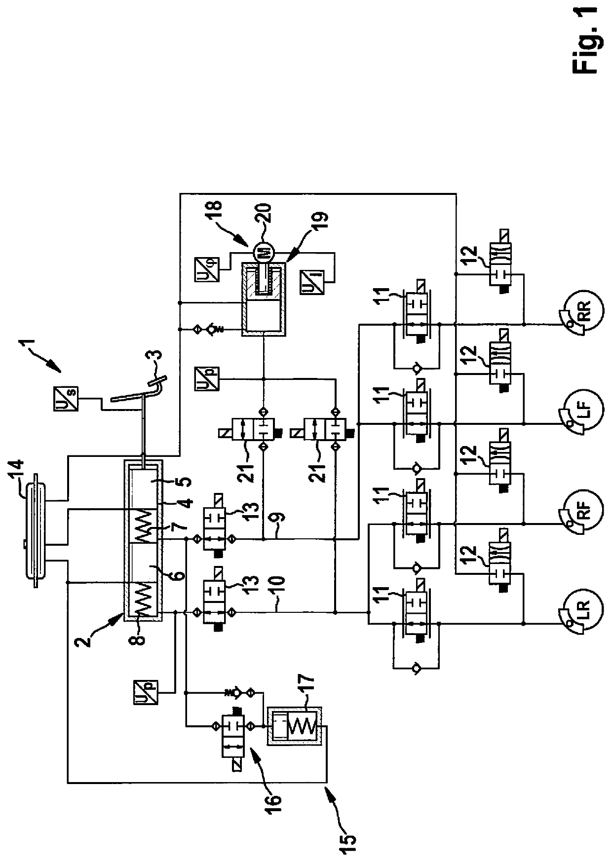
[0018]FIG. 1 shows, in a simplified representation, a brake system 1 for a motor vehicle (not shown in more detail). Brake system 1 has a master brake cylinder 2 that is realized as a tandem cylinder and can be actuated by a driver of the motor vehicle via a brake pedal 3. Master brake cylinder 2 has a hydraulic cylinder 4 in which a hydraulic piston 5, connected mechanically fixedly to brake pedal 3, and a further hydraulic piston 6 are each mounted so as to be axially displaceable. Between hydraulic piston 5 and further hydraulic piston 6 there is situated a spring element 7, and between further hydraulic piston 6 and an end face of hydraulic cylinder 4 there is situated a further spring element 8, axially preloaded, so that chambers that communicate with hydraulic connections of brake system 1 are formed respectively between hydraulic pistons 5 and 6 in hydraulic cylinder 4. In particular, two brake circuits 9 and 10 are connected to master brake cylinder 2 by the hydraulic conne...


PUM


Abstract

A master brake cylinder is described for a brake system of a motor vehicle as having a hydraulic cylinder that has a plurality of hydraulic connections, in which at least one hydraulic piston is mounted so as to be displaceable axially in a direction of actuation and in a relief direction, the hydraulic piston being displaceable against the force of a spring element in the direction of actuation, the hydraulic piston having at least one lateral wall opening that, in at least one sliding position, opens into an inner chamber of the hydraulic cylinder. It is provided that the lateral wall opening is assigned an elastically deformable sealing ring that on its inner side is fastened on the hydraulic piston and on its outer side is pre-loaded against the hydraulic cylinder by its inherent elasticity and is shaped such that when the hydraulic piston is displaced in the direction of actuation it detaches from the hydraulic cylinder, and when the hydraulic piston is displaced in the relief direction it bears on the hydraulic cylinder.

Description

FIELD OF THE INVENTION[0001]The present invention relates to a master brake cylinder for a brake system of a motor vehicle, having a hydraulic cylinder that has a plurality of hydraulic connections, in which cylinder at least one hydraulic piston is mounted so as to be displaceable axially in a direction of actuation and in a relief direction, the hydraulic piston being displaceable in the direction of actuation against the force of a spring element, and the hydraulic piston having at least one lateral wall opening that, in at least one sliding position, opens into an inner chamber of the hydraulic cylinder.[0002]In addition, the present invention relates to a brake system for a motor vehicle having a master brake cylinder that is connected to at least one hydraulic circuit that has at least one hydraulically actuatable wheel brake.BACKGROUND INFORMATION[0003]Master brake cylinders and brake systems of the type named above are known from the existing art. In order to convert the act...

Claims


Application Information

Patent Timeline
Patent Type & Authority Patents(United States)
IPC IPC(8): B60T11/236F15B7/08F16J15/3284B60T13/14F16J15/3236F15B15/14
CPCB60T11/236B60T13/142F15B7/08F15B15/1452F16J15/3236F16J15/3284B60T13/145B60Y2400/81
Inventor ANDERSON, CHRISFOERCH, DIRKYVONET, FLORENTSPROCQ, RAYNALDHANSMANN, SIMONKISTNER, MATTHIAS
Owner ROBERT BOSCH GMBH
Why Eureka
Try Eureka