Extendable sleeve for poured concrete deck

a technology of sleeve and concrete, which is applied in the field of extension sleeves for poured concrete decks, can solve the problems of raising health concerns, unable to meet the requirements of manufacturing to specific requirements, and labor-intensive methods for fastening flat strips to passage tubes

Active Publication Date: 2015-08-11
RELIANCE WORLDWIDE CORP
View PDF80 Cites 25 Cited by
  • Summary
  • Abstract
  • Description
  • Claims
  • Application Information

AI Technical Summary

Benefits of technology

[0024]Preferably the base has mating screw threads encircling the tubular cylinder of intumescent material and thus outward of that cylinder and accessible from the lower side of the base. To enable the screw threads to extend into the base and encircle the tubular cylinder of intumescent material the retaining clip is offset so that the tabs bend upward to form an offset accommodating the bottom screw threads with the tabs then extending outward through openings in the cylindrical sidewalls of the base that encircle the tubular cylinder of intumescent material. As needed, a removable adhesive cover or cap is placed over the bottom of the base to keep debris from entering the base during shipment, during installation, during pouring of the concrete and during application of fire retardant spray. The removable adhesive cover or cap may be removed and placed on the open end of an extension tube that is screwed into the bottom of the base if desired.

Problems solved by technology

The intumescent material often includes a graphite or fibrous material that can be messy and hazardous to handle and ingest, and often carcinogenic.
Fastening the flat strips to the passage tubes is labor intensive, prone to errors and may raise health concerns.
Further, because of the variable thickness of concrete slabs specified by builder contractors, manufacturers are forced to either custom build the container hardware or to supply containers in large increments that force customers to buy extra kits or cut the container on-site.
In any event, current options do not allow economically effective manufacturing-to-specification solutions.
Upon installation, the pipes actually used may differ from those initially planned or may be offset from the center more than the expansion of the intumescent material can accommodate, so the prefabricated, size specific fire seals may not fit, or fit as well as intended or needed, or may not work as well as designed during actual use.
Current passage tubes are premade to specific diameters and lengths, making it difficult to stock a sufficient supply for use and to accommodate variations in the passage tubes at the job site.
Providing a large base suitable for corrugated supports is expensive and unnecessary for plywood supports.
If the passage tube has a large base for use on a corrugated support, it becomes difficult to achieve the desired spacing when the large support is used on either plywood or corrugated supports.
Long passage tubes are sometimes cut shorter, wasting material and often resulting in inaccurate cuts as the worker may measure wrong.
Sometimes an extension can be added to a shorter passage tube to increase the overall length, but again workers can measure wrong, resulting in non-compliant passages through the concrete.
Also, the extended tubes may be hit, kicked or stood on and in such cases extension tubes may break.
If the pipes are too large for the holes the sheets tear, if the pipes are too small the seal is poor and if the pipes are offset from the holes in the sheets then inadequate seals may formed.
The concrete covering makes it difficult to locate the passage tubes.
But taping strands to things is time consuming, may be unintentionally omitted or not planned at all, and the tape may tear lose or otherwise fail to restrain the strands during pouring of the concrete or troweling.
Workers can sometimes look inside the passage tube to see the opening size in the water seal but that is time consuming, and invites error from judging opening diameters by visually looking down a dark tube of varying length.
After concrete floors are poured to entrain passage tubes there may be spills of large volumes of water.

Method used


Image

  • Extendable sleeve for poured concrete deck
  • Extendable sleeve for poured concrete deck
  • Extendable sleeve for poured concrete deck

Examples


Embodiment Construction

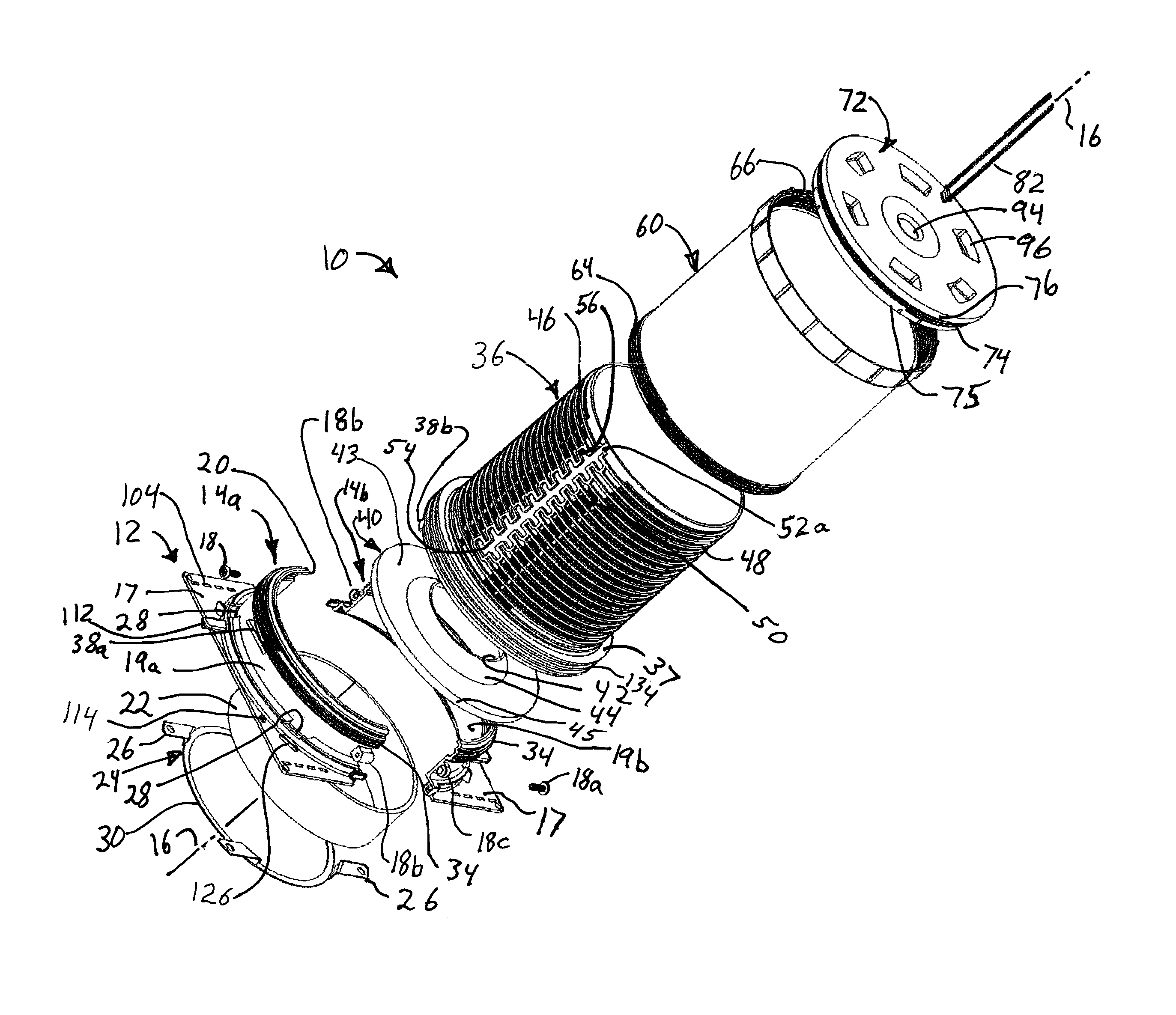
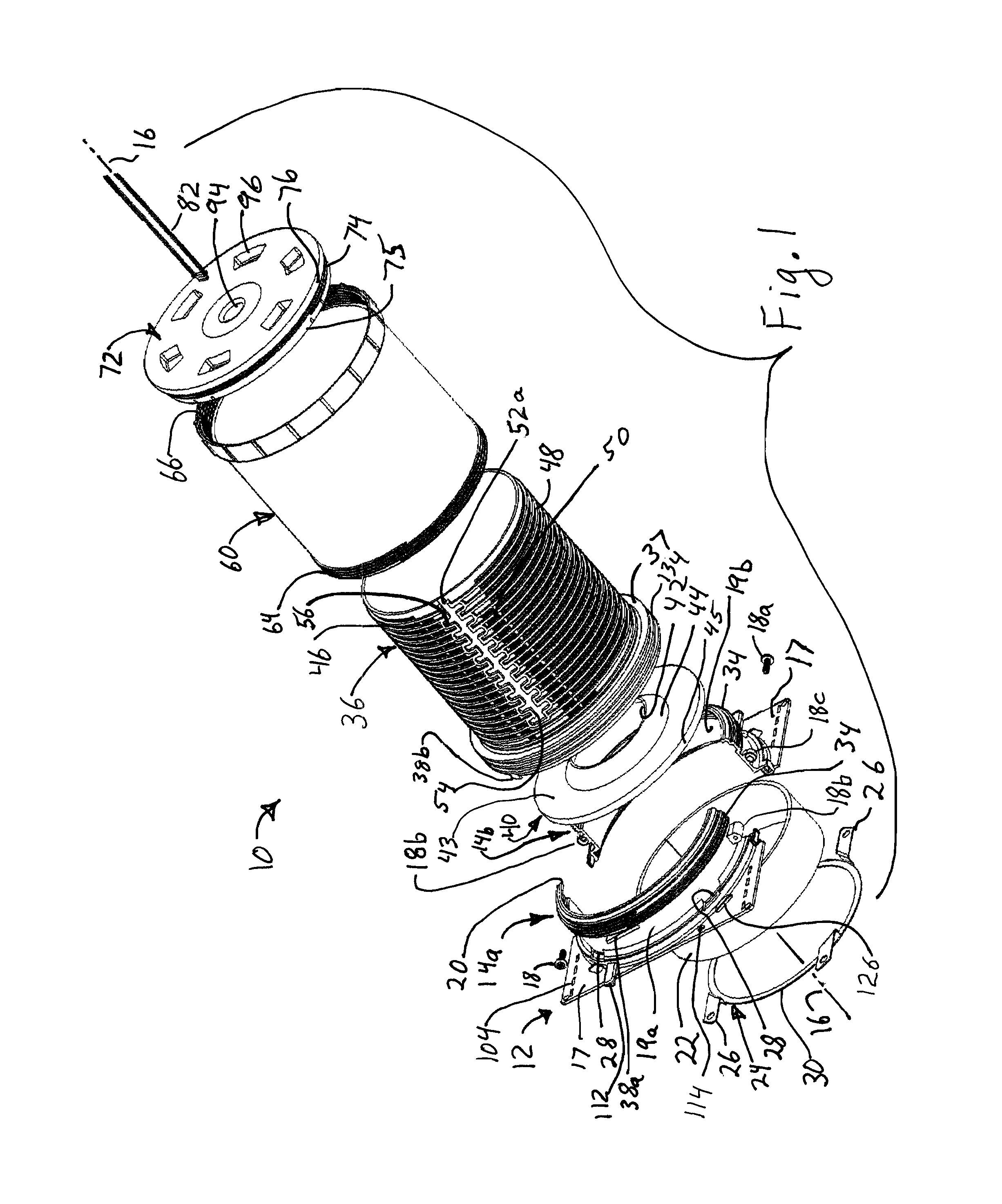
[0085]Referring to FIGS. 1-20 a passage tube assembly is provided having a base 12 formed of a housing 14 having two-parts 14a and 14b which clamp radially about a longitudinal axis 16 of the passage tube assembly 10 and base 12, with fasteners 18a clamping mating bosses 18b, 18c on opposing housing parts together in order to secure the housing parts 14a, 14b together. The base preferably has a flange 17 extending outward from the lower end of the base 12. As used herein, the relative terms inner and outer, inward and outward, are with respect to longitudinal axis 16. The relative terms above and below, upper or lower, upwards and downwards are also relative to the position along longitudinal axis 16 with respect to flange 17 on base 12 in the orientation of FIGS. 1 and 4-6, so that housing 14 and passage tube assembly are above base flange 17.

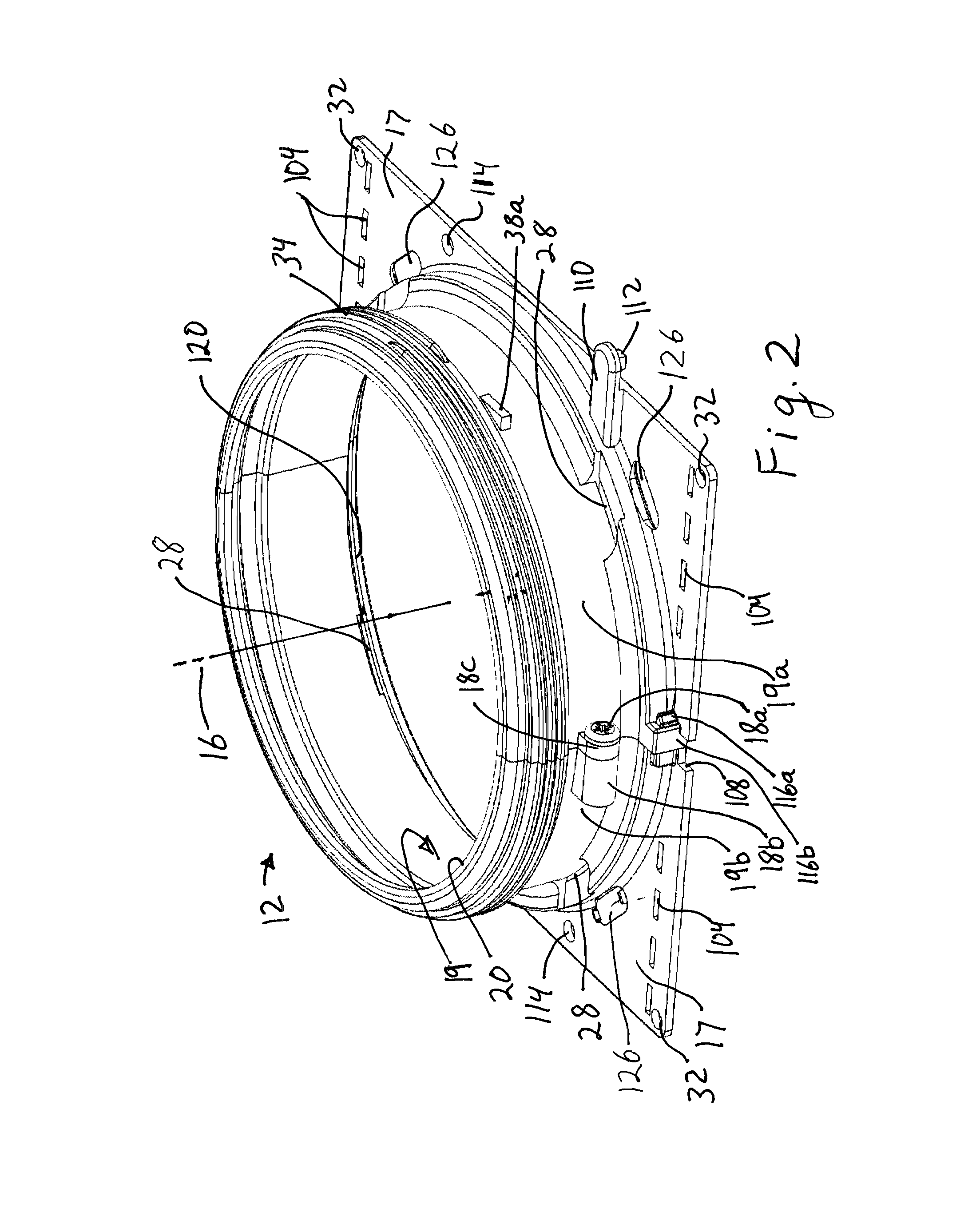
[0086]Referring especially to FIGS. 1-3 and 6, the housing parts 14a, 14b each have a curved sidewall extending along the longitudinal axis 1...


PUM


Abstract

A tubular passage for poured concrete decks has an intumescent tube held in a two-part, clamshell base. First and second, spaced apart, funnel shaped, diaphragm seals are connected to a first tubular passage or an adjustable length tubular extension. A cap for closing either tube has an inclined outer surface to form a beveled entrance to the passage in the concrete. An aerator box may be connected to the base. Hinged ends on the base allow the shape and length of support to be altered.

Description

CROSS-REFERENCE TO RELATED APPLICATIONS[0001]This application is a continuation in part of application Ser. No. 14 / 072,650, titled Extendable Sleeve for Poured Concrete Deck, filed Nov. 5, 2013, the complete contents of which are hereby incorporated by reference.STATEMENT RE: FEDERALLY SPONSORED RESEARCH / DEVELOPMENT[0002]Not ApplicableBACKGROUND[0003]Concrete floors in multistory buildings are poured onto flat plywood decks that are later removed, or poured onto corrugated sheet metal supports that are left in place. In both cases passages through the concrete decks are needed for various plumbing pipes, electrical conduits, ventilation tubes, etc. In the event of fire or flooding, these passages through the concrete must be sealed in order to prevent passage of air, smoke, fire or water. Current fire and smoke seals use an intumescent material that involves taking flat strips of intumescent material and fastening it around a cylindrical container of predetermined diameter using adh...

Claims


Application Information

Patent Timeline
Patent Type & Authority Patents(United States)
IPC IPC(8): E04C2/52E04B1/94A62C2/06H02G3/04F16L5/04F16L5/10E04B5/48E04F17/08
CPCE04B5/48F16L5/10E04F17/08F16L5/04H02G3/22E04B1/941A62C2/065E04B1/946E04B1/947H02G3/0412E04G15/061
Inventor MCCONNELL, TIMOTHY M.O'NEIL, VIRGILBROWN, LARRY D.HART, DENNIS L.
Owner RELIANCE WORLDWIDE CORP
Why Eureka
Try Eureka