Diaphragm for pressure sensor and pressure sensor

a technology for pressure sensors and diaphragms, which is applied in the direction of fluid pressure measurement using piezoelectric devices, fluid pressure measurement using elastically deformable gauges, instruments, etc., can solve the problems of thermal deformation of components, inducing errors in pressure value measurement, and inducing pressure value measurement errors, so as to reduce the risk of brittle fracture, and reduce the risk of aging deterioration

Inactive Publication Date: 2009-12-17
SEIKO EPSON CORP
View PDF17 Cites 27 Cited by
  • Summary
  • Abstract
  • Description
  • Claims
  • Application Information

AI Technical Summary

Benefits of technology

[0027]An advantage of the invention is to provide a diaphragm that bends and deforms upon receipt of a pressure, in particular to a diaphragm for a pressure sensor which is configured such that a portion joining the diaphragm to a housing of the pressure sensor is not susceptible to stress. The diaphragm allows suppression of aging deterioration, fewer occurrences of nonuniform compressive stress, and less susceptibility to brittle fracture. Another advantage of the invention is to provide a pressure sensor including this diaphragm. The pressure sensor does not use an oil that is a pressure receiving medium, and is a highly sensitive sensor that allows its manufacture through a fewer processes, its miniaturization, resistance to aging deterioration, and production of high yields.
[0028]The invention is designed to solve at least part of the aforementioned problems and may be achieved by the following aspects.
[0029]According to a first aspect of the invention, a diaphragm for a pressure sensor includes: a central section serving as a diaphragm body, the central section including: an external surface deformed upon receipt of an external pressure; and an internal surface transmitting a force to a pressure sensitive element inside a housing of the pressure sensor; a peripheral section that is outside of the central section and welded to an outer circumference of a pressure input orifice that is provided to the housing; and a step wall provided between the central section and the peripheral section, in that: the central section and the peripheral section are integrally and concentrically provided; and the diaphragm seals the pressure input orifice.
[0030]In this case, a stress due to deformation of the diaphragm may be concentrated on a boundary between the central section and the step wall, and the welded portion and the stress concentrated portion may be positionally separated. It is therefore possible to suppress transmission of the stress to the peripheral section to be weld-attached to the housing. Accordingly, even if cracks occur to a bead at the time of welding, growth of the cracks caused by the stress may be suppressed, and aging deterioration of the diaphragm may be reduced, that is, life of the diaphragm may be extended. Also, in this structure, a residual stress generated at the peripheral section by cooling after welding may be reduced in a step area. Therefore, it is possible to suppress nonuniform deformation of the central section and to suppress deterioration of sensitivity of the diaphragm.
[0031]It is preferable that, in the diaphragm for a pressure sensor according to the first aspect, the central section serving as the diaphragm body include a wall provided concentrically to the step wall.
[0032]When the diaphragm experiences a rapid pressure change, the diaphragm vibrates. However, by providing the wall, the vibration may be reflected inside the wall and trapped in an area inside, and the growth of cracks in the bead caused by transmission of the vibration may be suppressed.

Problems solved by technology

Therefore, these components may become thermally deformed due to a temperature change.
Such thermal deformation is an unwanted stress to the double-ended tuning fork resonator 509 and induces errors in measurement of pressure values.
If bubbles are generated in the oil 510 that serves as a pressure transmitting medium, a force cannot be stably transmitted through the force transmitting member 505 to the double-ended tuning fork resonator, thereby possibly inducing errors in the pressure value measurement.
Therefore, the related art pressure sensor using the oil 510 is not applicable to measurement of pressure of a pure liquid that dislikes foreign substances.
Furthermore, it is difficult to miniaturize the pressure sensor 502 of the related art because it includes the force transmitting member 605 having a complicated structure.
Also, because the force transmitting member 505 needs a flexible hinge having a slim constriction and is thus an expensive component, the manufacture of the pressure sensor becomes costly.
The pressure sensor of the fourth and fifth examples has a problem that, when the pressure sensor is inclined, the bellows thereof droops.
The force applied to the pressure sensitive element (the double-ended tuning fork resonator) therefore changes, leading to fluctuation of the resonance frequency.
If bubbles are generated in the oil, the oil serving as a pressure transmitting medium does not stably transmit the pressure through the pedestal to the double-ended tuning fork resonator, resulting in errors in the pressure measurement.
Therefore, if the diaphragm and the shaft are rigidly fixed, the mechanism may be damaged by thermal expansion that is different among the components.
Therefore, there is a very high possibility that this contact point deviates when the diaphragm and the shaft operate due to the pressure changes.
As the contact point deviates, a force acting on both the diaphragm and the shaft leaks out, resulting in less accurate pressure detection.
Accordingly, the sensor of these examples is not suitable for miniaturization.
Therefore, the measurement accuracy may not be increased.
Furthermore, the pressure sensor in the eighth and ninth examples is such that, when the laser or electron beam irradiation is stopped, the bead becomes thermally deformed due to rapid cooling and is therefore highly susceptible to cracks and the like.
If a pressure sensor having such a diaphragm is used, the bead becomes repeatedly deformed because of recurring deformation of the diaphragm that receives pressures from outside.
This makes the cracks to grow, leading to problems such as aging deterioration and damages in the diaphragm.
A residual stress generated at this time is concentrated on a central area of a pressure receiving part of the diaphragm, and the central area is nonuniformly deformed, leading to decrease in the sensitivity of the pressure sensor.
Furthermore, since the welding portion welds at a high welding temperature, it is exposed to high temperature in the laser irradiation and is therefore susceptible to brittle fracture.

Method used


Image

  • Diaphragm for pressure sensor and pressure sensor
  • Diaphragm for pressure sensor and pressure sensor
  • Diaphragm for pressure sensor and pressure sensor

Examples


fifth embodiment

[0097]According to this embodiment, in addition to the effects of the pressure sensor of the fifth embodiment described above, the following effects are produced. Specifically, when stress is applied, the stress is concentrated on the step part between the thick portion and a thin portion of the diaphragm body 114. The thick central area 116 is displaced up and down upon receipt of the stress, but since curving deformation of the central area 116 is small, the stress is not concentrated on a portion where the center shaft 36 is joined to the diaphragm 112. Consequently, the center shaft 36 is not affected by an unwanted force in a direction different from the force in the axis direction, and, therefore, pressure detection accuracy is improved.

seventh embodiment

[0098]FIG. 8 illustrates a pressure sensor 120 for relative pressure detection according to a The pressure sensor 120 uses the diaphragm 112 shown in FIG. 7.

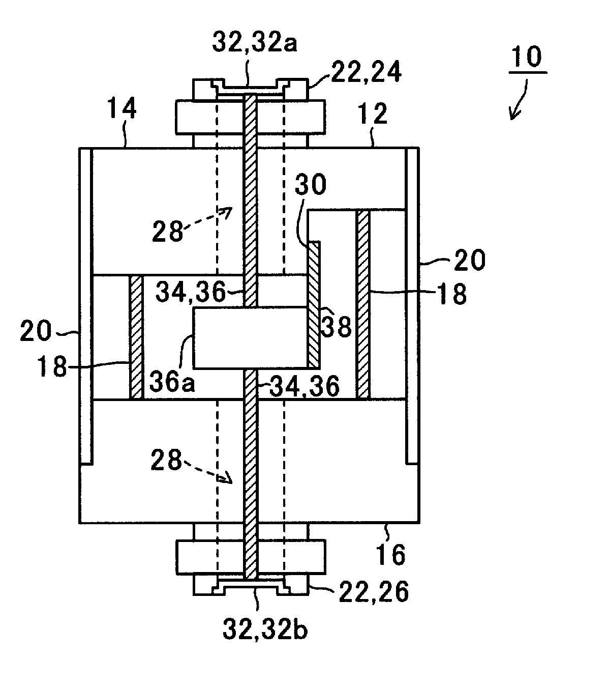
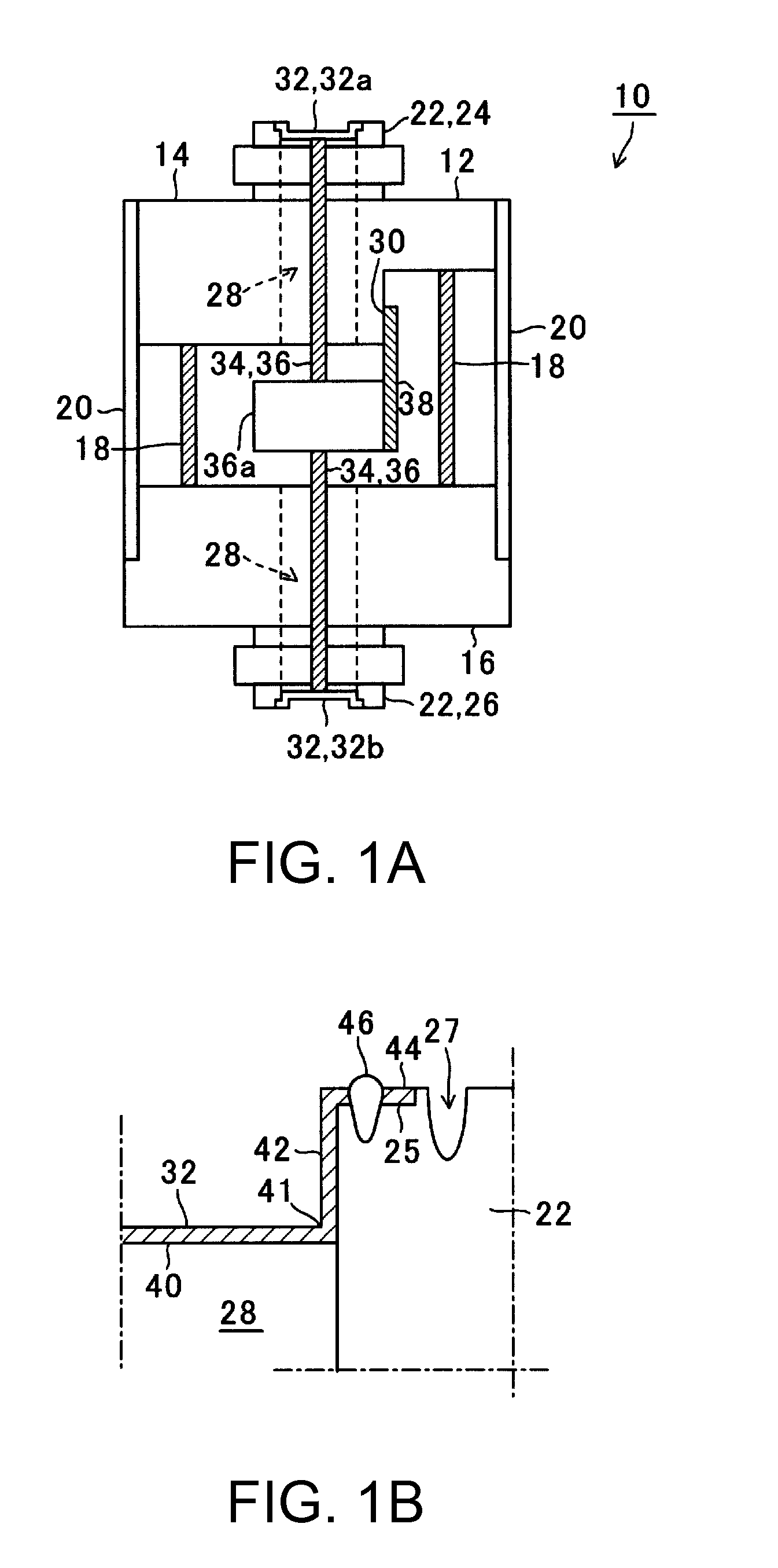
[0099]The pressure sensor 120 includes a housing 122 composed of a hollow cylindrical chassis. The housing 122 includes: a hermetic terminal board 124 as a first member (an upper end face plate), a flange end face plate 126 as a second member (a lower end face plate), and a cylinder sidewall 128 as a third member which surrounds the circumference of the end face plates separately disposed, so that the housing 122 has a structure of a hollow airtight container. On each outer surface of the hermetic terminal board 124 and the flange end face plate 126, a first pressure input orifice 130 and a second pressure input orifice 132 communicating with an internal space of the housing are provided as recesses. Through holes 134 (134, 134B) having the same axis as an axis core of the housing 122 are made through bottom plates of the herme...

eighth embodiment

[0107]FIG. 9 is a sectional view of a pressure sensor 160 according to an The example shown in the drawing is an example of a pressure sensor for detecting absolute pressure using the diaphragm 112 shown in FIG. 7.

[0108]The pressure sensor 160 includes a housing 152 composed of a hollow cylindrical chassis. The housing 152 includes: a hermetic terminal board 154 as a first member (an upper end face plate), a flange end face plate 156 as a second member (a lower end face plate) that is the same as that in the seventh embodiment, and a cylinder sidewall 158 as a third member surrounding the circumference of the end face plates that are separately disposed by the cylinder sidewall 158, so that the housing 152 has a structure of a hollow sealed container. In the flange end face plate 156, a pressure input orifice 160 communicating with the inner space is penetrated coaxially with an axis core of the housing 152, thereby forming a recess. Provided in the center of the recess is a throug...


PUM

PropertyMeasurementUnit
external pressureaaaaaaaaaa
forceaaaaaaaaaa
pressureaaaaaaaaaa

Abstract

A diaphragm for a pressure sensor includes: a central section serving as a diaphragm body, the central section including: an external surface deformed upon receipt of an external pressure; and an internal surface transmitting a force to a pressure sensitive element inside a housing of the pressure sensor; a peripheral section that is an exterior of the central section and welded to an outer circumference of a pressure input orifice that is provided to the housing; and a step wall provided between the central section and the peripheral section. The central section and the peripheral section are integrally and concentrically provided. The diaphragm seals the pressure input orifice.

Description

BACKGROUND[0001]1. Technical Field[0002]The present invention relates to a diaphragm for a pressure sensor and to a pressure sensor having the diaphragm. The invention is particularly suitable for suppression of aging deterioration of the diaphragm.[0003]2. Related Art[0004]Pressure sensors that use a piezoelectric resonator as a pressure sensitive element are known as a water pressure gauge, an air gauge, and a differential pressure gauge. The piezoelectric resonator includes, for instance, an electrode pattern on a plate-like piezoelectric substrate, and a direction in which a force is detected is set to be a detecting axis. When pressure is applied in the direction of the detecting axis, a resonance frequency of the piezoelectric resonator changes, and the pressure is detected by using the changes in the resonance frequency. JP-A-56-119519, JP-A-64-9331, and JP-A-2-228534, as a first, second, and third examples, disclose a pressure sensor including a piezoelectric resonator as a ...

Claims


Application Information

Patent Timeline
Patent Type & Authority Applications(United States)
IPC IPC(8): G01L9/08
CPCG01L9/0022G01L19/0046G01L13/025G01L7/08G01L19/14
Inventor MOTOYAMA, HISAO
Owner SEIKO EPSON CORP
Why Eureka
Try Eureka