Rotor for Vertical Wind Power Station

a technology for wind power stations and rotors, applied in the direction of propellers, propulsive elements, water-acting propulsive elements, etc., can solve problems such as performance losses, and achieve the effects of enhancing the lift effect of individual rotor elements, favorable surface patterning, and additional utilization of wind for

Inactive Publication Date: 2013-08-29
MOSER JOSEF
View PDF1 Cites 7 Cited by
  • Summary
  • Abstract
  • Description
  • Claims
  • Application Information

AI Technical Summary

Benefits of technology

[0034]These lug-type lift elements serve to enhance the lift effect of the individual rotor elements, with the airflow bringing about an additional utilization of the wind force, even while disengaging from the rotor, by means of the lift elements.
[0035]Such lug-type lift elements are typically also camb...

Problems solved by technology

However, a higher performance of a lift rotor in the upper speed range is offset by a conversely lower starting torque of the rotor at standstill.
Owing to their particular suitability for wind power stations having relatively low power yields in the range from 1 to 10 kW, vertical rotors have hitherto not found acceptance yet for a utilization in power generation on an industrial scale.
Up to the present, however, hybrid rotors such as the hybr...

Method used


Image

  • Rotor for Vertical Wind Power Station
  • Rotor for Vertical Wind Power Station
  • Rotor for Vertical Wind Power Station

Examples


Embodiment Construction

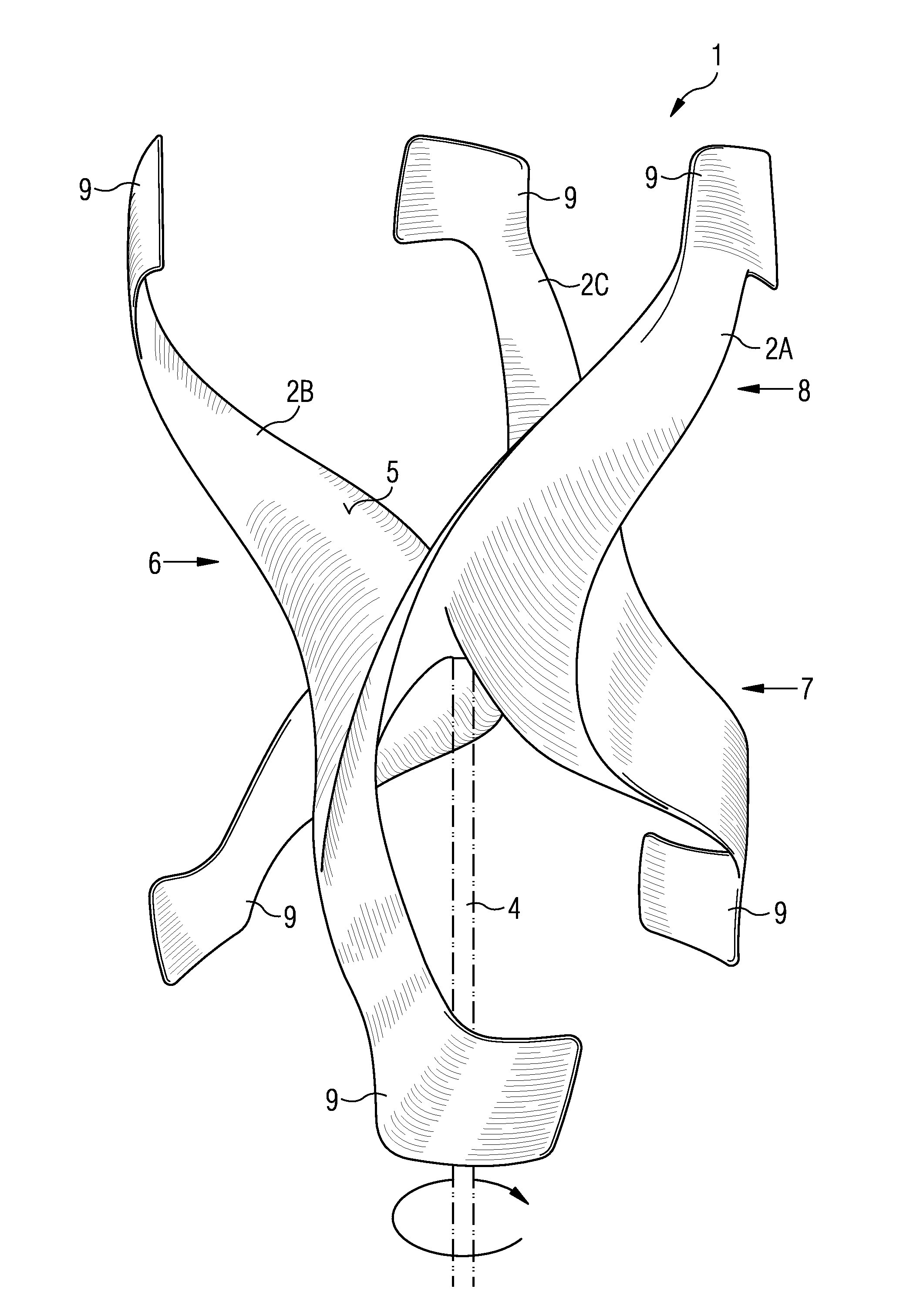
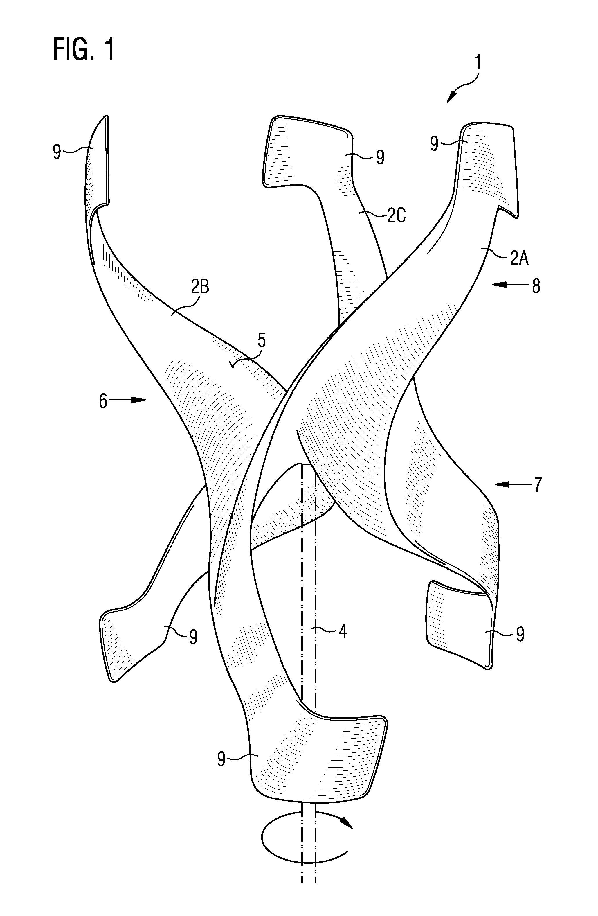
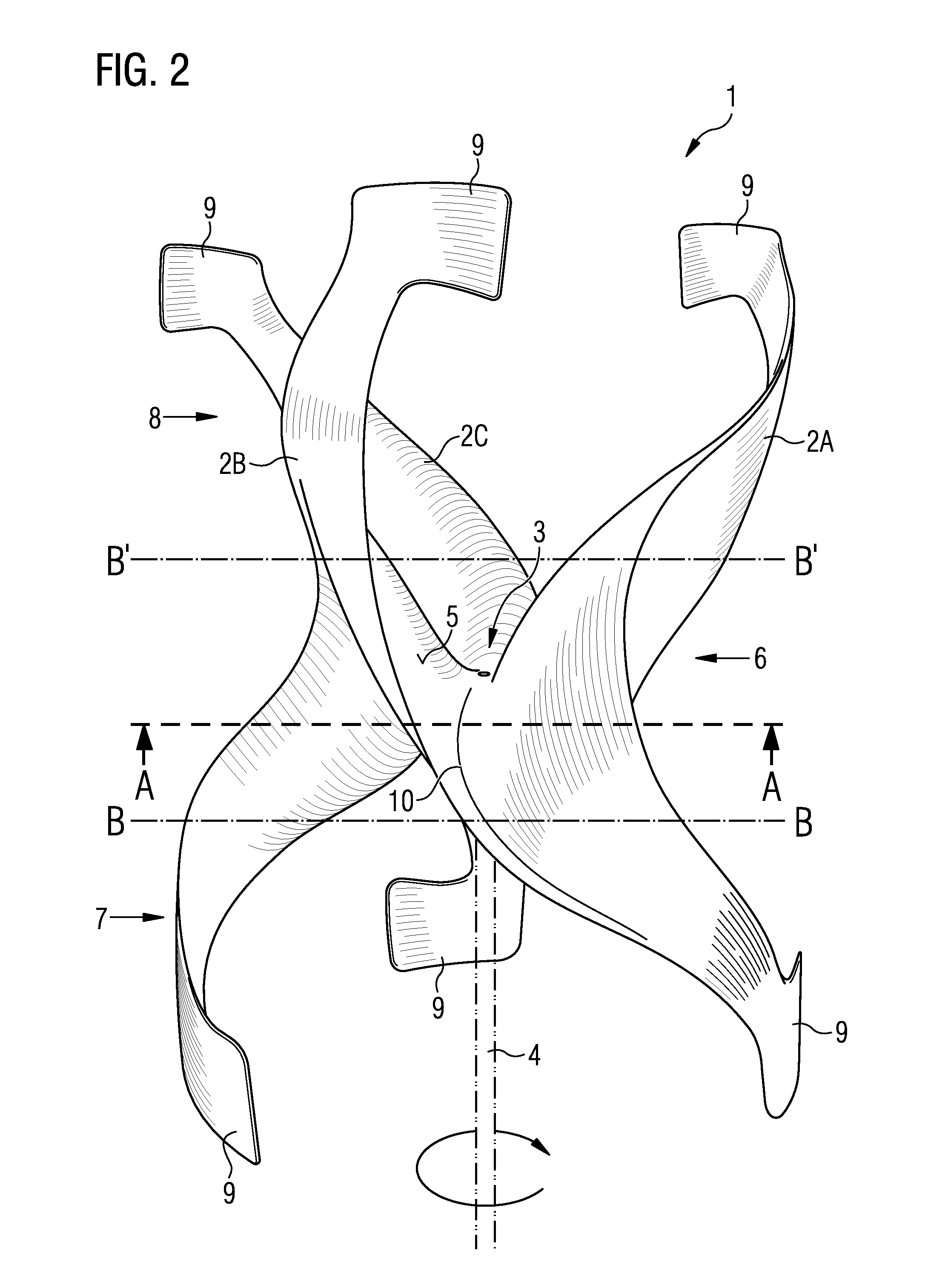
[0045]In the figures, 1 designates an example of a rotor for a vertical wind power station comprising triple-surface rotor elements 2A, 2B, 2C that are arranged around a hub region 3. The rotor elements 2A, 2B, 2C have a helical axis which, in the exemplary case, is parallel to the axis of rotation 4 of the rotor 1 and around which the rotor elements 2A, 2B, 2C are twisted in a spiraling manner. The rotor elements 2A, 2B, 2C have concave and convex surface regions smoothly merging into each other and having different radii of curvature along the helical axis.

[0046]The rotor 1 is frictionally coupled to the axis of rotation 4. As the rotor 1 is a vertical rotor for a vertical wind power station, the axis of rotation 4 is arranged in the direction of gravity during operation.

[0047]At the lower end (not shown in the figures) of the axis of rotation 4, a gearbox is provided which is connected to a generator that is equally caused to rotate by the rotation of the rotor 1 and in a manner ...


PUM


Abstract

The present invention relates to a rotor for a vertical wind power station comprising a plurality of planar rotor elements (2A, 2B, 2C) that are arranged around a hub region (3), wherein the rotor elements (2A, 2B, 2C) have a helical axis which is parallel or inclined relative to an axis of rotation (4) of the rotor (1) and around which the rotor elements (2A, 2B, 2C) are twisted in a spiraling manner, the rotor elements (2A, 2B, 2C) having concave and convex surface regions smoothly merging into each other and having different radii of curvature along the helical axis.

Description

PRIORITY CLAIM[0001]This application is a United States Non-provisional Application claiming priority under 35 U.S.C. §119 from German Patent Application No. DE 102012203138.3, filed Feb. 29, 2012, the entire contents of which are herein incorporated by reference.FIELD OF THE INVENTION[0002]The present invention relates to a rotor for a vertical wind power station in comprising a plurality of planar rotor elements that are arranged around a hub region, characterized in that the rotor elements have a helical axis which is parallel or inclined relative to an axis of rotation of the rotor and around which the rotor elements are twisted in a spiraling manner, the rotor elements having concave and convex surface regions smoothly merging into each other and having different radii of curvature along the helical axis and further as demonstrated by FIG. 1.BACKGROUND OF THE INVENTION[0003]A number of different rotor types for wind power stations have been described and tested in the prior art...

Claims


Application Information

Patent Timeline
IPC IPC(8): F03D3/06
CPCF03D3/065F05B2240/211Y02E10/74F05B2250/15F05B2250/71F05B2240/32F03D3/061F03D3/062
Inventor MOSER, JOSEF
Owner MOSER JOSEF
Why Eureka
Try Eureka