

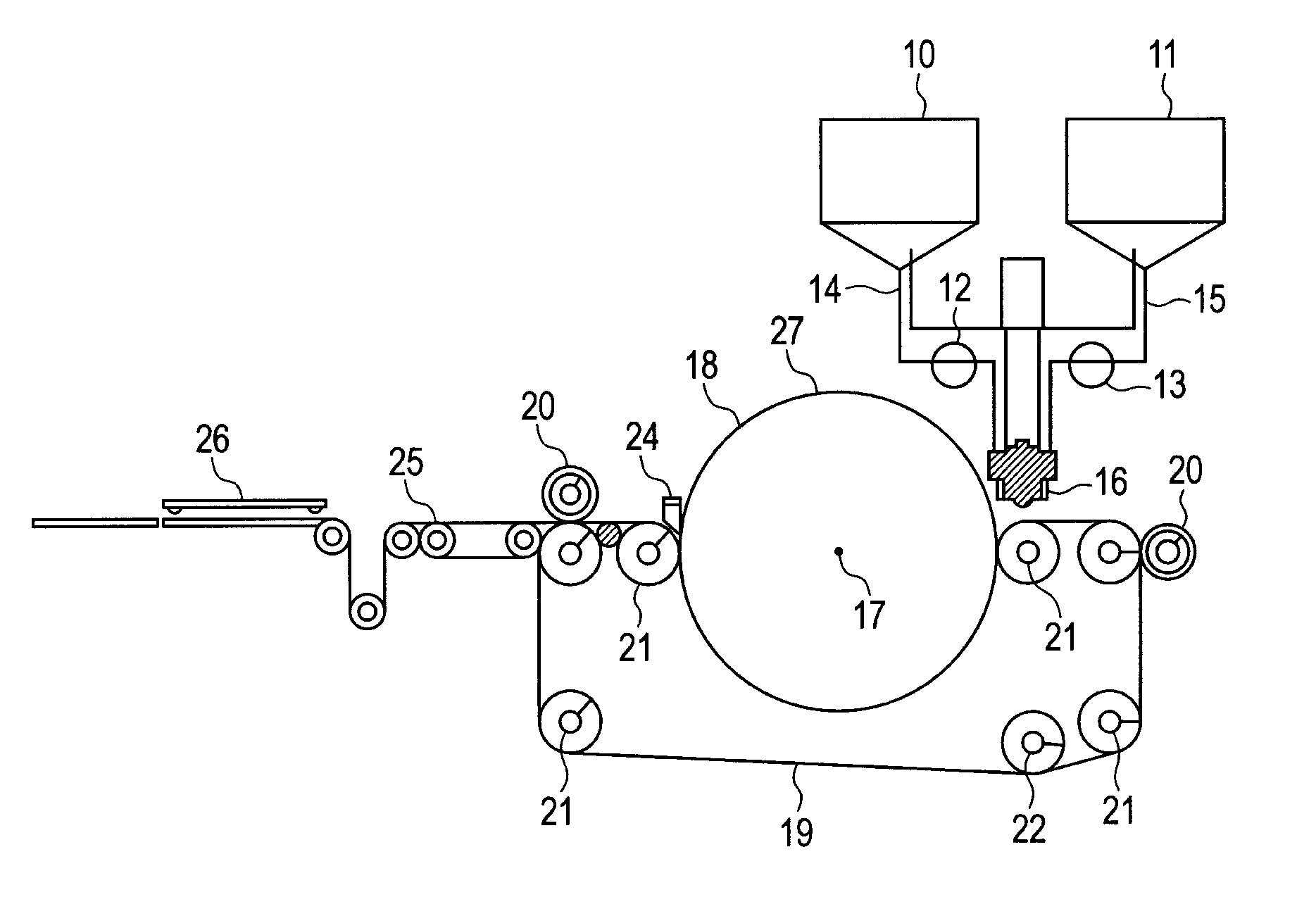
Method and apparatus for producing an electrophotographic blade member
a technology of electrophotography and blade parts, which is applied in the direction of applications, manufacturing tools, instruments, etc., can solve the problems of increasing the size of the entire apparatus, increasing the space to be ensured, and the difficulty of continuous automation, so as to reduce the appearance of marks, less irregularities of physical properties, and less intrusion.
- Summary
- Abstract
- Description
- Claims
- Application Information
AI Technical Summary
Benefits of technology
Problems solved by technology
Method used
Image

Examples
example 1
PBA2000
(Preparation of Thermosetting Polyurethane Composition)
32.0 parts by mass of 4,4′-diphenylmethane diisocyanate (MDI) and 61.0 parts by mass of polybutylene adipate polyester polyol (PBA) having a molecular weight of 2,000 were caused to react for 3 hours under an 80° C. nitrogen atmosphere, yielding a prepolymer containing NCO at 8.8%. On the other hand, 3.9 parts by mass of 1,4-butanediol (1,4-BD), 3.2 parts by mass of trimethylolpropane (TMP), and a urethane-curing catalyst were mixed, yielding a curing agent. An isocyanurate-forming catalyst and a urethane-forming catalyst were used as curing catalysts. There was used, as a polyurethane-curing catalyst, an isocyanurate-forming catalyst with the product name of “P15” (a potassium acetate solution in ethylene glycol (EG), produced by Air Products Japan, Inc.). In this case, the isocyanurate-forming catalyst was blended so as to account for 80 ppm of the resultant polyurethane composition. Further, there was used, as a uretha...
example 2
PBA2000 and PBA1000
27.7 parts by mass of 4,4′-diphenylmethane diisocyanate (MDI) and 52.7 parts by mass of polybutylene adipate polyester polyol (PBA) having a molecular weight of 2,000 were caused to react for 3 hours under an 80° C. nitrogen atmosphere, yielding a prepolymer containing NCO at 8.8%. On the other hand, 14.9 parts by mass of PBA having a molecular weight of 1,000 (product name “NIPPOLLAN 4009” (produced by Nippon Polyurethane Industry Co., Ltd.)), 2.6 parts by mass of 1,4-butanediol (1,4-BD), 2.1 parts by mass of trimethylolpropane (TMP), and the same curing catalysts as those used in Example 1 were mixed, yielding a curing agent. The curing catalysts were contained at the same ratios as those in Example 1. The thus obtained polyurethane composition was subjected to the same processes as those in Example 1, to thereby produce a developer amount regulating blade. The developer amount regulating blade was evaluated in the same manner as that in Example 1. Table 1 shows...
example 3
PEA2000
A developer amount regulating blade was produced in the same manner as that in Example 1, except that polyethylene adipate polyol (PEA) having a number average molecular weight of 2,000 (product name “NIPPOLLAN 4040” (produced by Nippon Polyurethane Industry Co., Ltd.)) was used as the polyol (B), and the feeding amounts were changed to those listed in Table 1. Further, evaluation was performed in the same manner as that in Example 1. Table 1 shows the results of the evaluation.
PUM
| Property | Measurement | Unit |
|---|---|---|
| viscosity | aaaaa | aaaaa |
| viscosity | aaaaa | aaaaa |
| viscosity | aaaaa | aaaaa |
Abstract
Description
Claims
Application Information