
Direct-light backlight module with assisting solar light and liquid crystal display device

a backlight module and solar light technology, applied in the field of thin film transistor liquid crystal display, can solve the problems of so-called second lens technology meeting a dead end, and achieve the effect of reducing the overall power of led and being readily convenient for the backlight module to coll

Inactive Publication Date: 2015-08-11
TCL CHINA STAR OPTOELECTRONICS TECH CO LTD
View PDF2 Cites 0 Cited by
  • Summary
  • Abstract
  • Description
  • Claims
  • Application Information

AI Technical Summary

Benefits of technology

[0006]It is the objective of the present invention to provide a direct light backlight module with assisting solar light source and a liquid crystal display device incorporated with such as backlight module, and in which solar light can be used as an assistant light source such that the LCD made therefrom can save more energy and environmental friendly.
[0035]The present invention can be concluded with the following advantages.
[0036]With the implementation of an assisting solar light source into the present invention, the solar light can be served as an assisting light source benefiting the brightness of the backlight module such that during the daytime, the solar light can be used as a light source; while in the cloudy and nighttime, the LED light source can be used as the main light source. Accordingly, the overall power of the LED can be reduced so as to meet the standard of the environmental friendly.
[0037]By providing an optical connector on the backlight module, it is readily convenient for the backlight module to collect the solar light source during the daytime. The collected solar light can be readily served as the assisting light source.

Problems solved by technology

However, if the energy saving is pushed further, then the so-called second lens technology will also meet a dead end.

Method used


Image

  • Direct-light backlight module with assisting solar light and liquid crystal display device
  • Direct-light backlight module with assisting solar light and liquid crystal display device

Examples


Embodiment Construction

[0041]Detailed description will be given in view of preferred embodiments made in accordance with the present invention.

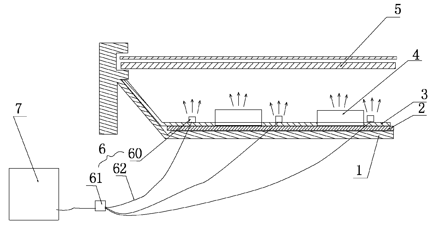
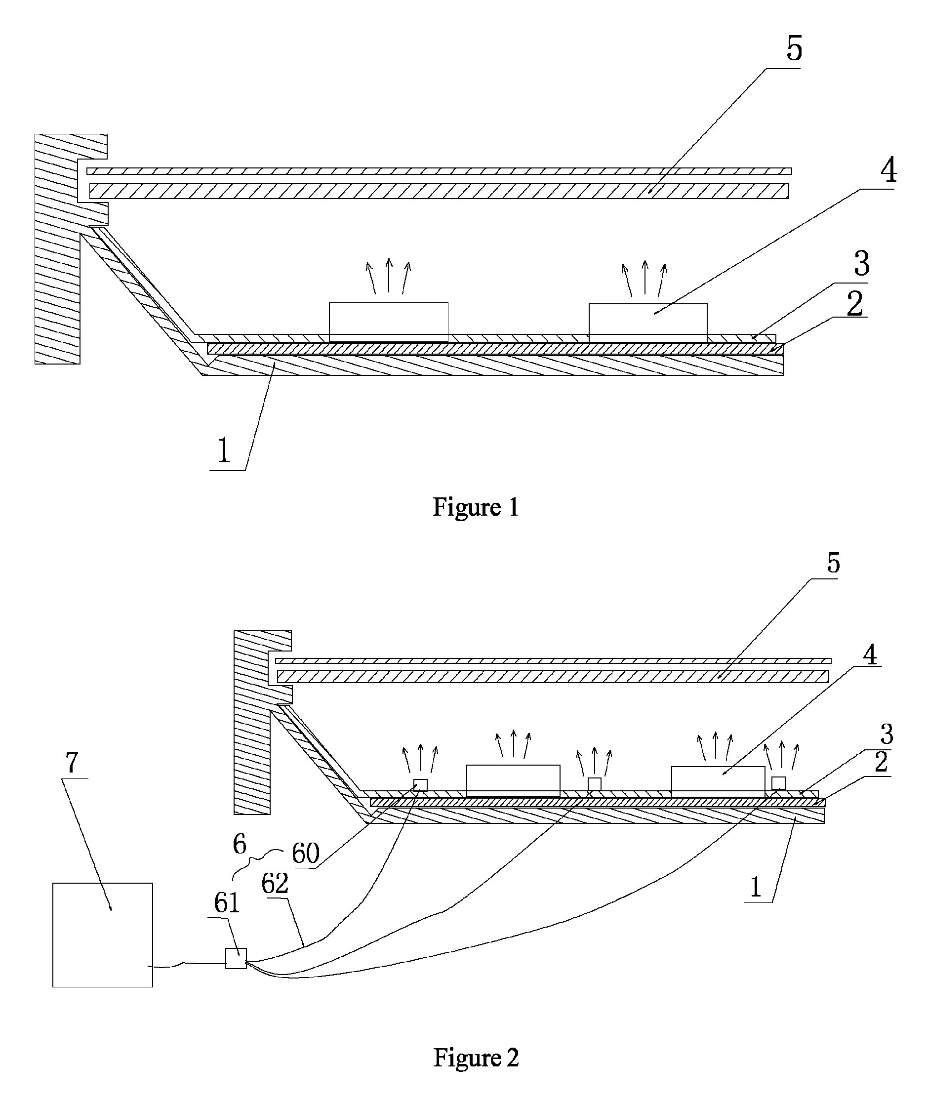
[0042]Referring to FIG. 2, which is an illustrational view of a backlight module made in accordance with the present invention. The direct light backlight module with assisting solar light source includes at least the following elements.

[0043]A backboard 1 is provided.

[0044]The backboard 1 is provided with a printed circuit board 2 and a waveguide 3.

[0045]A backlight module 4 is disposed on the waveguide 4, and configured with a plurality of LED and is connected to the printed circuit board 2 through the waveguide 3.

[0046]An optical film module 5 is disposed above the waveguide 3 while facing the emitted light from the light source 4. The optical film module 5 includes a plurality of optical films, such as a diffuser or a prism. By this arrangement, the brightness of the light beam emitted from the emitting surface of the waveguide is bright and homogeneous which c...


PUM

PropertyMeasurementUnit
energyaaaaaaaaaa
brightnessaaaaaaaaaa
poweraaaaaaaaaa

Abstract

The present invention provides a direct light backlight module with solar light assistance, which comprises a backboard. The backboard is provided with a waveguide. A light source is disposed under the waveguide. An optical film module is disposed above the waveguide and faces the light emitted from the direct light source. An assisting light source device is provided and which collects solar light and direct it to an optical film module. The present invention further provides a liquid crystal display device with the direct light backlight module with assisting solar light. With the provision of the assisting light source, the solar light can be used as an assisting light source making the backlight module and the liquid crystal display device made therefrom become more environmental friendly.

Description

CROSS REFERENCE[0001]This application is claiming a priority arisen from a patent application, entitled with “Direct-Light Backlight Module with Assisting Solar Light and Liquid Crystal Display Device”, submitted to China Patent Office on Nov. 12, 2012, designated with an Application No. 201210448482.8. The whole and complete disclosure of such patent application is hereby incorporated by reference.FIELD OF THE INVENTION[0002]The present invention relates to a thin film transistor liquid crystal display, also known as TFT-LCD, and more particular to a direct light backlight module with assisting solar light source and also a liquid crystal display made with such a backlight module.[0003]Currently, the light source used in a backlight module of a TFT-LCD is typically an LED (light emitting diode) for which is featured with energy saving and comparably high performance.[0004]As shown in FIG. 1, which is an illustrational and structural view of a backlight module, and which includes a ...

Claims


Application Information

Patent Timeline
Patent Type & Authority Patents(United States)
IPC IPC(8): G02F1/133F21V8/00G02F1/1335
CPCG02B6/0006G02F1/133602G02B6/0008G02B6/0068G02F2001/133618G02F1/133618
Inventor HU, CHE-CHANGHE, HU
Owner TCL CHINA STAR OPTOELECTRONICS TECH CO LTD
Learn More