Portable apparatus and portable timepiece

a technology of portable equipment and timepiece, which is applied in the direction of electric winding, instruments, and horology, can solve the problems of excessive rotation of locking parts, parts or rotary rings, and the inability to prevent the ingress of debris into the female and male threaded parts,

Active Publication Date: 2015-08-11
SEIKO INSTR INC
View PDF10 Cites 79 Cited by
  • Summary
  • Abstract
  • Description
  • Claims
  • Application Information

AI Technical Summary

Benefits of technology

[0016]It is an object of the present invention to provide a portable apparatus and a portable timepiece which can, in a state where a locking member is moved to a locked position where pushing of a push button is prevented, prevent the locking member from being rotatably operated excessively in error.

Problems solved by technology

Further, there has been also known a prior art where the external appearance of the push button does not change between a locked state and an unlocked state and, further, the intrusion of debris into the female and male threaded portions is made difficult even in a locked state (see JP-A-2004-319446 (patent literature 2), for example).
There may be a case where, after the locking member reaches the locked position, the locking member having the female threaded portion or the rotary ring is further rotatably operated excessively due to an operator's error.
Accordingly, it is scarcely possible for a user to perceive that the locking member has reached the locked position due to the elastic deformation of the retainer ring.
When the locking member or the rotary ring is rotatably operated excessively in error, there may be a case where the deformed retainer ring is pulled into the inside of the pipe along with such a rotary operation.
As a result, there may be a case where the smooth movement of the push button in the axial direction is impaired after the erroneous operation.
Further, the drawbacks brought about by the above-mentioned erroneous operation become a cause of impairment in designing the locking member or the rotary ring with a larger outer diameter.
However, such a countermeasure uses a dedicated retainer ring which is yet to be developed and hence, a manufacturing cost is pushed up.
In addition, an operation of mounting a retainer ring on a shaft portion of a push button or an operation of removing the retainer ring from the shaft portion of the push button becomes cumbersome so that operability is largely lowered when a push button and parts around the push buttons are disassembled and cleaned.
Accordingly, the above-mentioned countermeasures are not desirable.

Method used


Image

  • Portable apparatus and portable timepiece
  • Portable apparatus and portable timepiece
  • Portable apparatus and portable timepiece

Examples


first embodiment

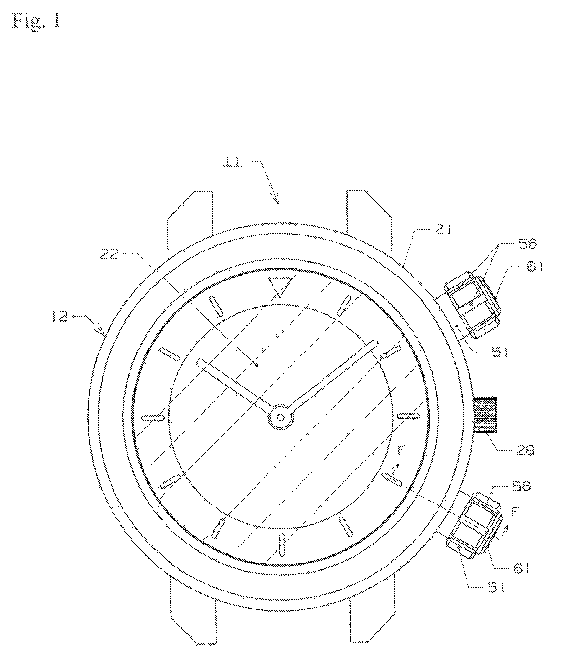
[0051]the present invention is explained in conjunction with FIG. 1 to FIG. 4.

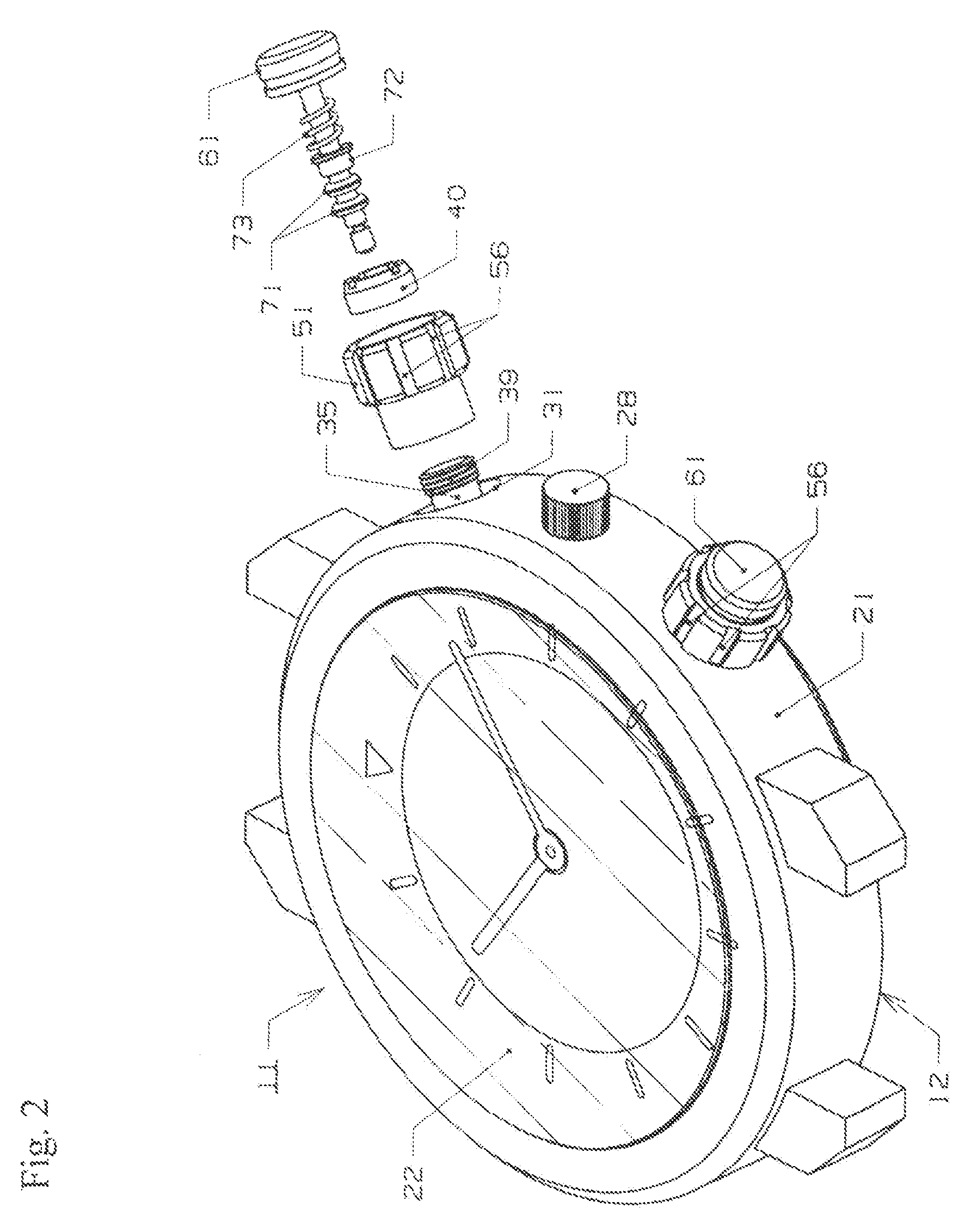
[0052]In FIG. 1 to FIG. 4, symbol 11 indicates a potable apparatus such as a portable timepiece, to be more specific, a wrist watch which is used as a waterproof timepiece. The timepiece 11 includes an apparatus exterior body, for example, a timepiece exterior body 12.

[0053]As shown in FIG. 3 and FIG. 4, in the inside of the timepiece exterior body 12, predetermined members are housed. The predetermined members include: a display board such as a dial 13, for example; an apparatus which controls a display such as a movement 14 which controls the movement of time indicating pointers, for example; a lamp not shown in the drawing; and a battery not shown in the drawing which is provided as a power source.

[0054]The movement 14 includes at least one, for example, two button response members, for example, contacts 15 (only one contact shown in FIG. 2 and FIG. 4). Each contact 15 is formed of a leaf spring or the ...

third embodiment

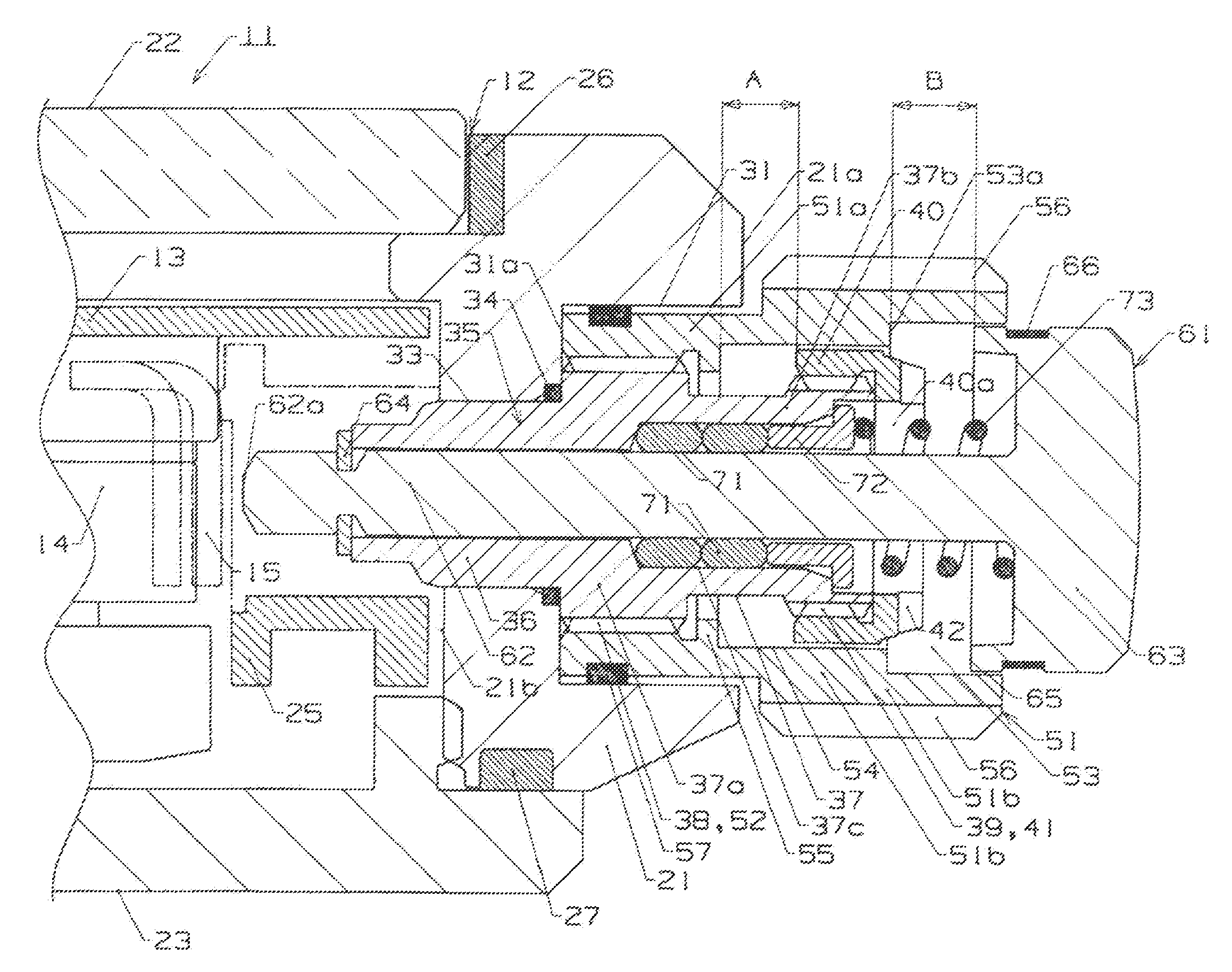
[0113]In the third embodiment, a locking portion 55 of a locking member 51 is formed such that the locking portion 55 partitions a bottom of an intermediate recessed portion 54 and occupies an area ranging from the partitioned portion of the bottom of the intermediate recessed portion 54 to a distal end surface of a small-diameter portion 51a. An inner diameter of the locking portion 55 is smaller than an inner diameter of the intermediate recessed portion 54. A side surface 55a of the locking portion 55 also functions as a bottom surface of the intermediate recessed portion 54.

[0114]The side surface 55a is used as an engaging surface which is brought into contact with and is separated from the stopper portion 40. Further, a female threaded portion 52 is formed on the inner periphery of the locking portion 55. The locking member 51 is mounted on the pipe 35 by threadedly engaging the female threaded portion 52 thereof with a male threaded portion 38 formed on a pipe 35. The third em...

fourth embodiment

[0117]In the fourth embodiment, a stopper portion 40 is integrally formed on the outer periphery of a small-diameter portion 37b of an externally arranged sleeve portion 37 of a pipe 35. An outer diameter of the stopper portion 40 is set larger than an outer diameter of a male threaded portion 38.

[0118]Further, in the fourth embodiment, the locking member 51 is formed of two members, that is, a first member element 51c and a second member element 51d.

[0119]That is, the first member element 51c has a ring shape. A female threaded portion 52 which is threadedly engaged with a male threaded portion 38 of a pipe 35 is formed on the inner periphery of the first member element 51c, and a locking portion 55 is formed on the first member element 51c at a position displaced from the female threaded portion 52. An inner diameter of the locking portion 55 is slightly larger than an outer diameter of the male threaded portion 38 formed on the pipe 35. A male threaded portion 51f is formed on t...


PUM


Abstract

A pushbutton of a portable apparatus is locked against inward axial movement by engagement with a locking member when the locking member is unthreaded a distance A from the apparatus body and brought into abutment with a fixed stopper member. The pushbutton is released from its locked state when the locking member is threaded into the apparatus body and brought out of abutment with the stopper member and into abutment with the apparatus body. In its unlocked state, a head portion of the pushbutton is axially spaced a distance B from an opposedly facing portion of the locking member, wherein A≦B.

Description

BACKGROUND OF THE INVENTION[0001]1. Field of the Invention[0002]The present invention relates to a portable apparatus and a portable timepiece provided with a push button.[0003]2. Description of the Related Art[0004]Among portable timepieces such as a wrist watch or a pocket watch or portable apparatuses such as a stop watch, a mobile phone or a personal digital assistant, there has been known a portable timepiece or a portable apparatus where a push button which operates a contact or the like in the inside of an apparatus exterior body is mounted on the apparatus exterior body. By pushing the push button with a predetermined stroke, for example, in the portable timepiece, a dial can be illuminated, or a time display can be changed from an analogue display to a digital display or from a digital display to an analogue display, or date and day which are digitally displayed can be corrected.[0005]This type of portable apparatus is configured such that the push button is biased in the d...

Claims


Application Information

Patent Timeline
Patent Type & Authority Patents(United States)
IPC IPC(8): G04B29/00G04B37/00H01H1/06H01H13/06H01H3/12H01H13/14H01H13/70H01H9/20G04B3/00G04B3/04G04C3/00G04B37/10H01H13/52
CPCH01H9/20G04B3/001G04B3/043G04B3/046G04C3/001H01H3/12H01H13/06G04B37/106H01H13/52H01H2225/016G04G21/00H01H13/04H01H13/14
Inventor HIRANUMA, HARUKITAKEDA, KOREMOTO
Owner SEIKO INSTR INC
Why Eureka
Try Eureka