Imaging apparatus and driving method selecting one of a phase difference AF mode and a contrast AF mode
a technology of af mode and af mode, applied in the direction of color television details, television system details, television systems, etc., can solve the problem of deteriorating af precision
- Summary
- Abstract
- Description
- Claims
- Application Information
AI Technical Summary
Benefits of technology
Problems solved by technology
Method used
Image
Examples
first embodiment
[0045]FIG. 5 is a flowchart illustrating the AF mode selection processing sequence which is performed in step S3 of FIG. 4. First, in step S23, the subject size (AF region) is determined and it is determined whether a predetermined number of phase difference detection pixels are included in a horizontal size of a subject size imaged on the light receiving surface of the solid-state imaging device.
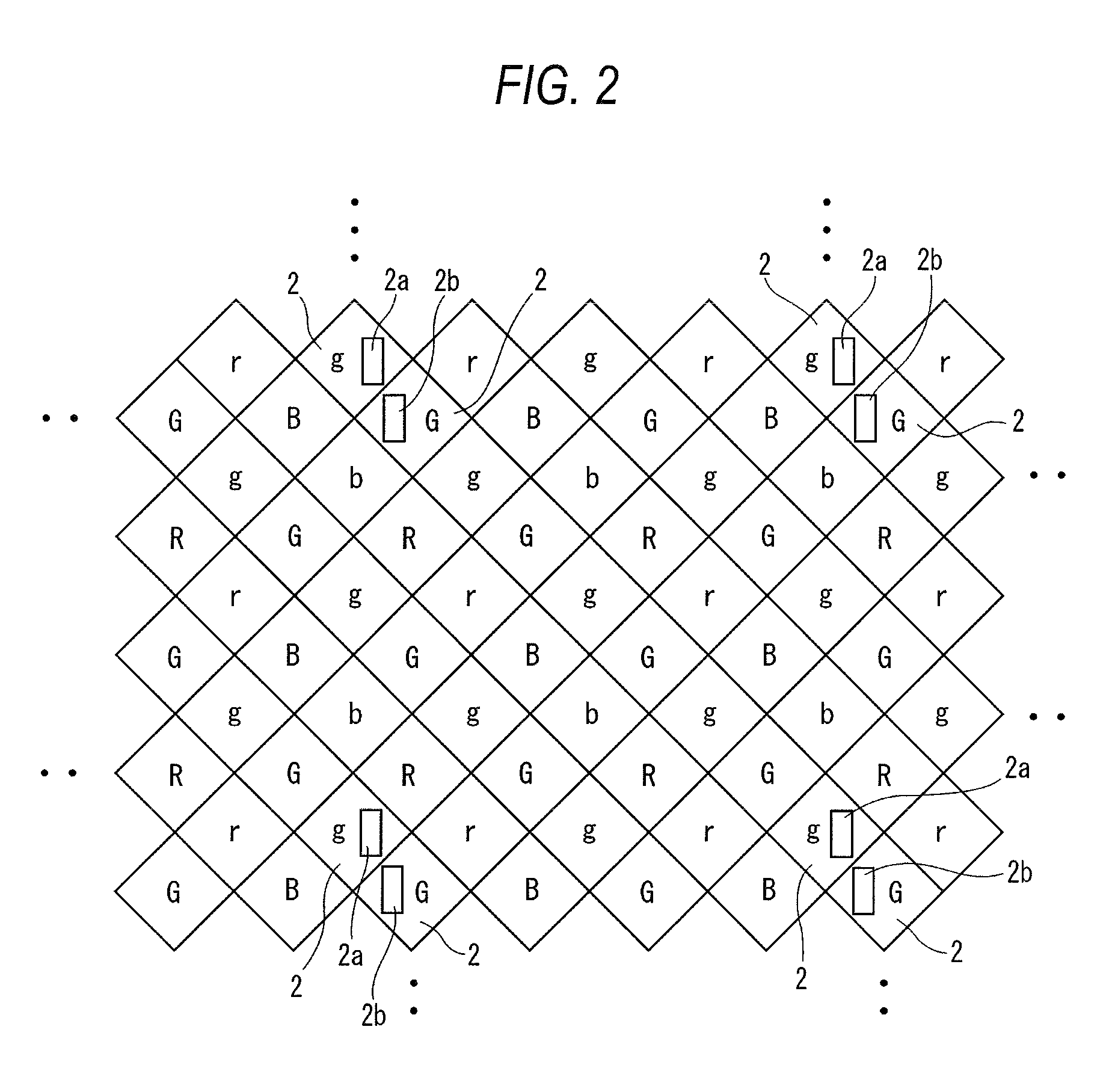
[0046]The phase difference detection pixel is included at a ratio of one pixel per four horizontal pixels, and when 100 phase difference detection pixels are required in order to secure the AF precision, it is determined whether a horizontal direction of the size of the subject imaged on the light receiving surface of the solid-state imaging device is equal to or more than 400 pixels in step S23.
[0047]According to a result of the judgment in step S23, in the case where the number of the horizontal pixels of the subject size is less than 400 pixels, when the AF processing is performed by th...
second embodiment
[0049]FIG. 6 is a flowchart illustrating an AF mode selection processing sequence according to the present invention. In the embodiment, step S22 is provided before step S23 of FIG. 5. In step S22, it is determined whether the subject in the AF region has a periodic pattern and when the subject has the periodic pattern, the process proceeds to step S31 to select the contrast AF mode. When the subject does not have the periodic pattern, the process proceeds to step S23 from step S22 to determine the subject size as above.
[0050]When it is determined that the subject size is less than 400 pixels in step S23, the process proceeds to next step S24, and a contrast of the main subject image and a contrast of a circumferential image (for example, a region excluding the main subject from 400 horizontal pixels and a predetermined range of the number of vertical pixels) of the main subject are compared with each other.
[0051]In step S24, when it is determined that the subject contrast>the circu...
third embodiment
[0054]FIG. 7 is a flowchart illustrating an AF mode selection processing sequence according to the present invention. In the embodiment, step S25 is executed after step S24 of FIG. 6. That is, when it is determined that the subject contrast24, the process proceeds to step S25 to determine whether the contrast of the main subject image is higher than a predetermined threshold value α.
[0055]When the contrast is high, the phase different AF mode is selected even though the size of the main subject image is small (step S32, the AF region in this case is as large as the subject size or slightly smaller than the subject size) and when the contrast is low, the process proceeds to step S31 to select the contrast AF.
[0056]When the contrast is high even though the subject size is small, sufficient AF precision may be acquired even though the phase difference AF mode is executed in the small AF region. As a result, the subject applied with the phase difference AF mode is expanded, and as a res...
PUM
 Abstract
Description
Claims
Application Information
 - R&D
- Intellectual Property
- Life Sciences
- Materials
- Tech Scout
- Unparalleled Data Quality
- Higher Quality Content
- 60% Fewer Hallucinations
Browse by: Latest US Patents, China's latest patents, Technical Efficacy Thesaurus, Application Domain, Technology Topic, Popular Technical Reports.
© 2025 PatSnap. All rights reserved.Legal|Privacy policy|Modern Slavery Act Transparency Statement|Sitemap|About US| Contact US: help@patsnap.com


