Dust collector with spark arrester

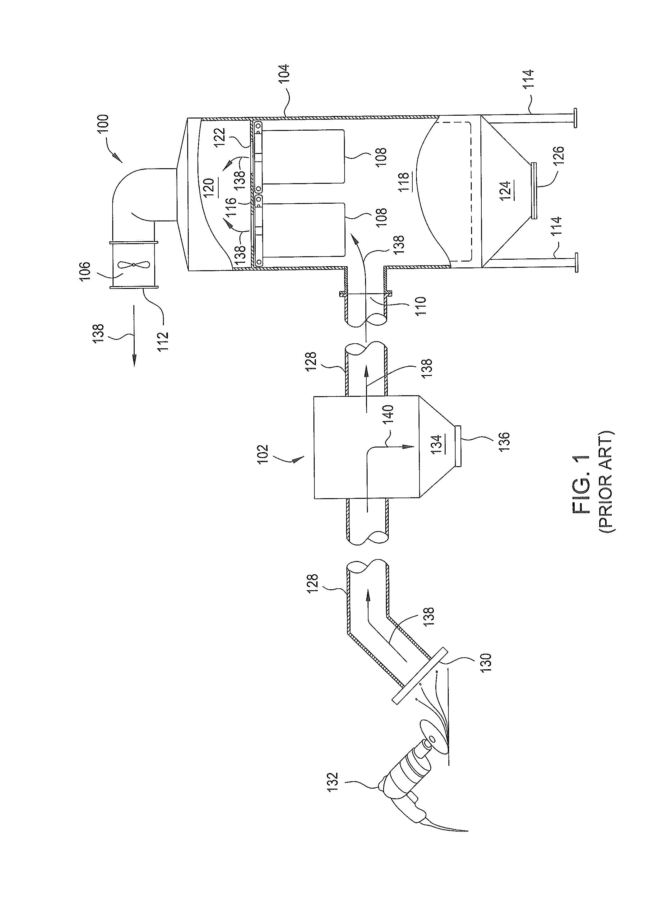
a technology of spark arrestor and dust collector, which is applied in the direction of dispersed particle separation, separation process, chemistry apparatus and processes, etc., can solve the problems of time-consuming and difficult maintenance of the conventional spark arrestor 102

Inactive Publication Date: 2015-08-18
CAMFIL USA
View PDF5 Cites 0 Cited by
  • Summary
  • Abstract
  • Description
  • Claims
  • Application Information

AI Technical Summary

Problems solved by technology

This makes the conventional spark arrestor 102 difficult and time consuming to maintain, particularly if the ductwork containing the spark arrestor is not easily accessible.

Method used


Image

  • Dust collector with spark arrester
  • Dust collector with spark arrester
  • Dust collector with spark arrester

Examples


Embodiment Construction

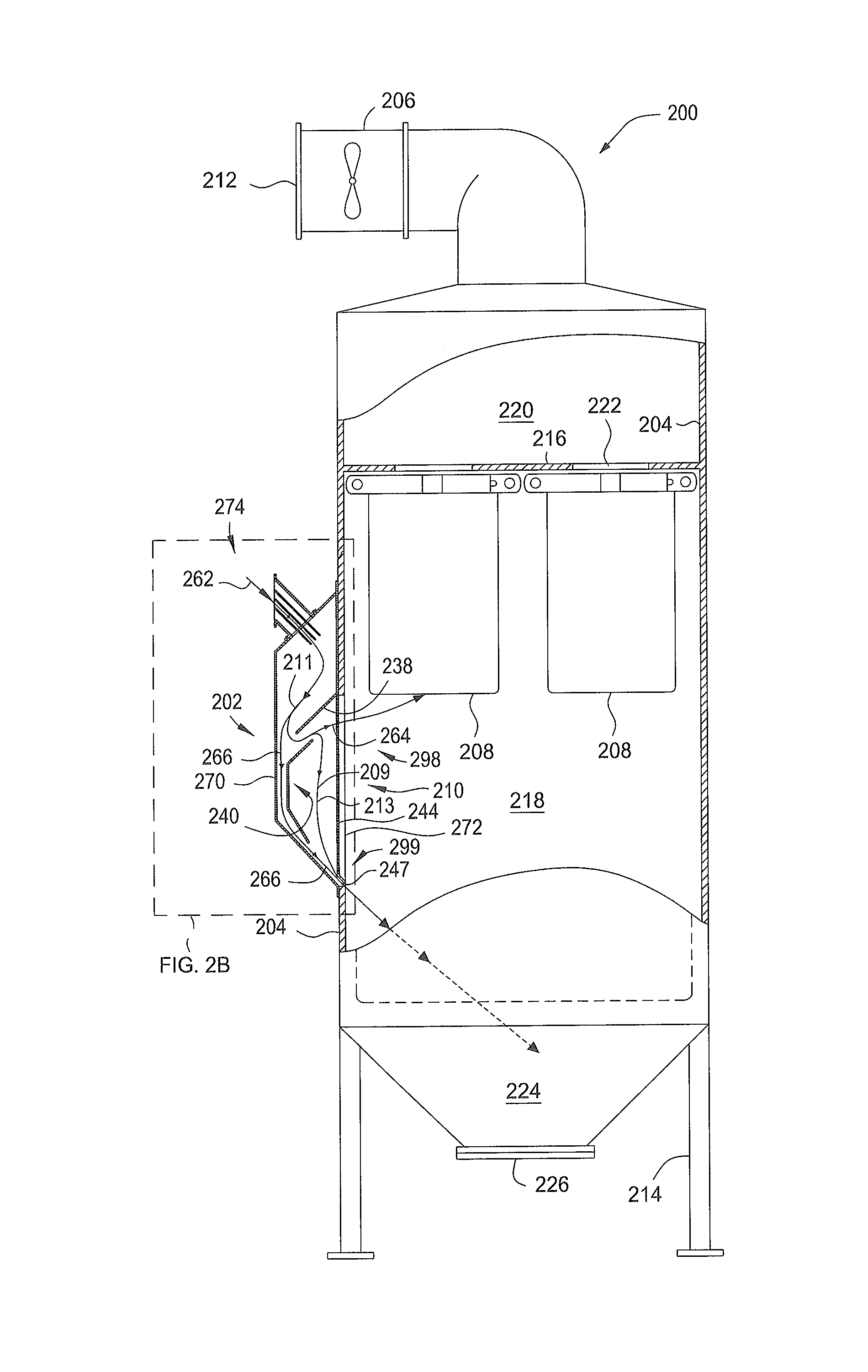
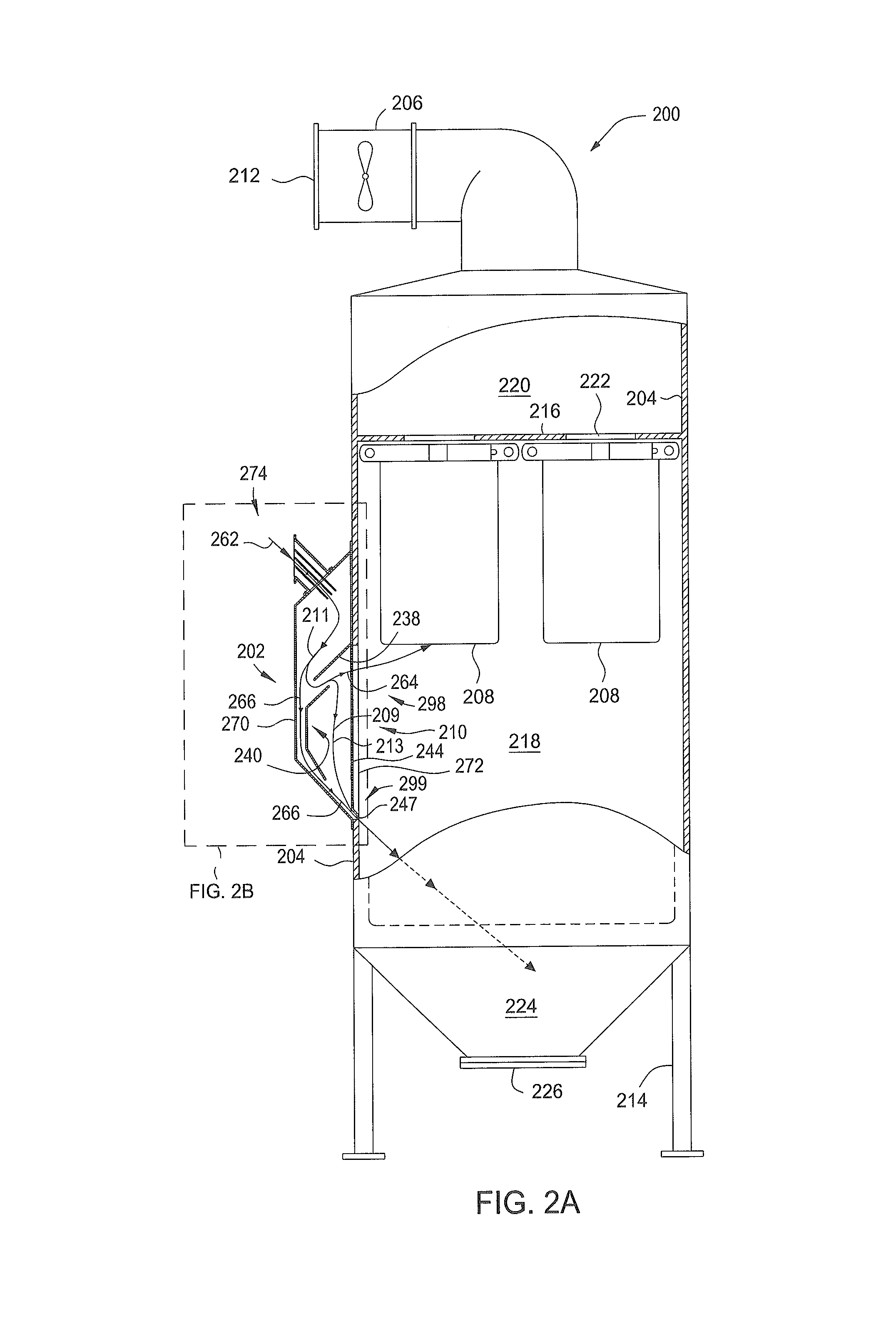
[0024]FIG. 2A is a partial cut away elevation of one embodiment of a spark arrestor 202 coupled to a dust collector 200. Although the spark arrestor 202 as illustrated is used in an exemplary embodiment of the dust collector 200, it is contemplated that embodiments of spark arrestors described herein may be utilized in dust collectors of varying designs, including those available from different manufactures. The spark arrestor 202 may also be provided integrally with new dust collectors or be added to existing dust collectors present in the field.

[0025]The dust collector 200 is similar to the dust collector 100 and includes a housing 204 that is coupled to an air mover 206, such as a fan or blower, for drawing air through at least one replaceable air filter 208 mounted in the housing 204. The air mover 206 may be mounted to or be remote from the housing 204. The housing 204 is constructed from a rigid material suitable to withstand the operational pressures and loading for which the...


PUM

PropertyMeasurementUnit
angleaaaaaaaaaa
angleaaaaaaaaaa
angleaaaaaaaaaa

Abstract

A spark arrestor and dust arrestor for same are provided. In one embodiment, the spark arrestor includes a housing having an inlet and an outlet, wherein the outlet is positioned on a dust arrestor mounting side of the housing, and a turn baffle disposed in the housing in a position that creates a tortuous flow path through the housing between the inlet and the outlet. The tortuous flow path includes a low inertia channel formed in the housing having an orientation that directs particles passing through the low inertia channel through an upper portion of the outlet of the housing, and a high inertia channel formed in the housing, wherein a downstream portion of the high inertia channel has an orientation that directs particles passing through the high inertia channel through a lower portion of the outlet of the housing.

Description

BACKGROUND[0001]1. Field[0002]The present invention relates to a spark arrester and a dust collector for use with same.[0003]2. Description of the Related Art[0004]In many dust collector systems, a spark arrestor is employed in the ductwork upstream of a dust collector to prevent combustible materials, such as sparks, from entering into the dust collector and damaging the air filters mounted in the dust collector. Common applications for spark arrestors include dust collectors for use in welding, plasma cutting, laser cutting, metal reclaiming and processing, and other spark producing operations.[0005]FIG. 1 illustrates a partial cut away elevation of a conventional dust collector 100 coupled in series with a conventional spark arrestor 102. The dust collector 100 includes a housing 104 that is coupled to an air mover 106, such as a fan or blower, for drawing air, as shown by arrows 138, from a work place 132 through at least one replaceable air filter 108 mounted in the housing 104...

Claims


Application Information

Patent Timeline
Patent Type & Authority Patents(United States)
IPC IPC(8): B01D45/00B01D45/08B01D50/00B01D46/24
CPCB01D45/08B01D46/2403B01D50/002B01D50/20B01D46/0093
Inventor WALTERS, MICHAEL C.
Owner CAMFIL USA
Why Eureka
Try Eureka