Exhaust device equipped with spark arrester

a technology of exhaust device and spark arrester, which is applied in the direction of room acoustics, filtration separation, separation process, etc., can solve the problems of affecting the shape of each part, the number of parts is more likely to increase, and the fastening work is more likely to be complicated, so as to prevent damage or sound, easy to support the spark arrester, and prevent the effect of damag

Active Publication Date: 2021-07-27
HONDA MOTOR CO LTD
View PDF17 Cites 0 Cited by
  • Summary
  • Abstract
  • Description
  • Claims
  • Application Information

AI Technical Summary

Benefits of technology

[0006]Accordingly, an object of the present invention is to easily support a spark arrester and prevent an occurrence of damage or sound in the spark arrester due to the effect of an exhaust pressure or external vibration.
[0012]According to the present invention, the spark arrester includes a net-like main body part through which exhaust gas passes, and a flange part with a diameter enlarged from the main body part, at least the flange part being formed of a spring member. The flange part includes a bent part that is telescopically bent by elastic deformation in a direction along a flow of the exhaust gas. The bent part is supported in a state where the elastic deformation of the bent part is allowed. Therefore, it is possible to easily support the spark arrester by using the elasticity of the bent part, and to prevent an occurrence of damage or sound in the spark arrester due to the effect of an exhaust pressure or external vibration.
[0013]The bent part has a structure in which a part of the flange part is bent toward one of an upstream side and a downstream side of the exhaust gas. Therefore, the bent part can be easily provided.
[0014]The flange part is a member formed by bending, as the bent part, three outer peripheral portions at intervals in a circumferential direction toward one of an upstream side and a downstream side of the exhaust gas with respect to an annular plate material in a front view. Therefore, the flange part can be easily fabricated.
[0015]The exhaust device includes an exhaust port through which the exhaust gas is exhausted, and the spark arrester is provided at a position where an external appearance is visible from the exhaust port. Therefore, the state of the spark arrester can be easily checked.
[0016]The spark arrester is provided at a position where a part of the spark arrester projects from the exhaust port depending on an exhaust gas pressure acting on the spark arrester. Therefore, a clogged state or the like of the spark arrester can be easily checked.

Problems solved by technology

However, in the fastening structure, the number of parts is more likely to increase, a fastening work is more likely to be complicated, and the shape of each part is more likely to be complicated.
On the other hand, in the nipping structure, the clearance depending on the spark arrester is required, the spark arrester vibrates due to the effect of the external vibration or exhaust pressure of an engine or the like, and the spark arrester contacts another member, which may cause damage or sound.

Method used


Image

  • Exhaust device equipped with spark arrester
  • Exhaust device equipped with spark arrester
  • Exhaust device equipped with spark arrester

Examples


first embodiment

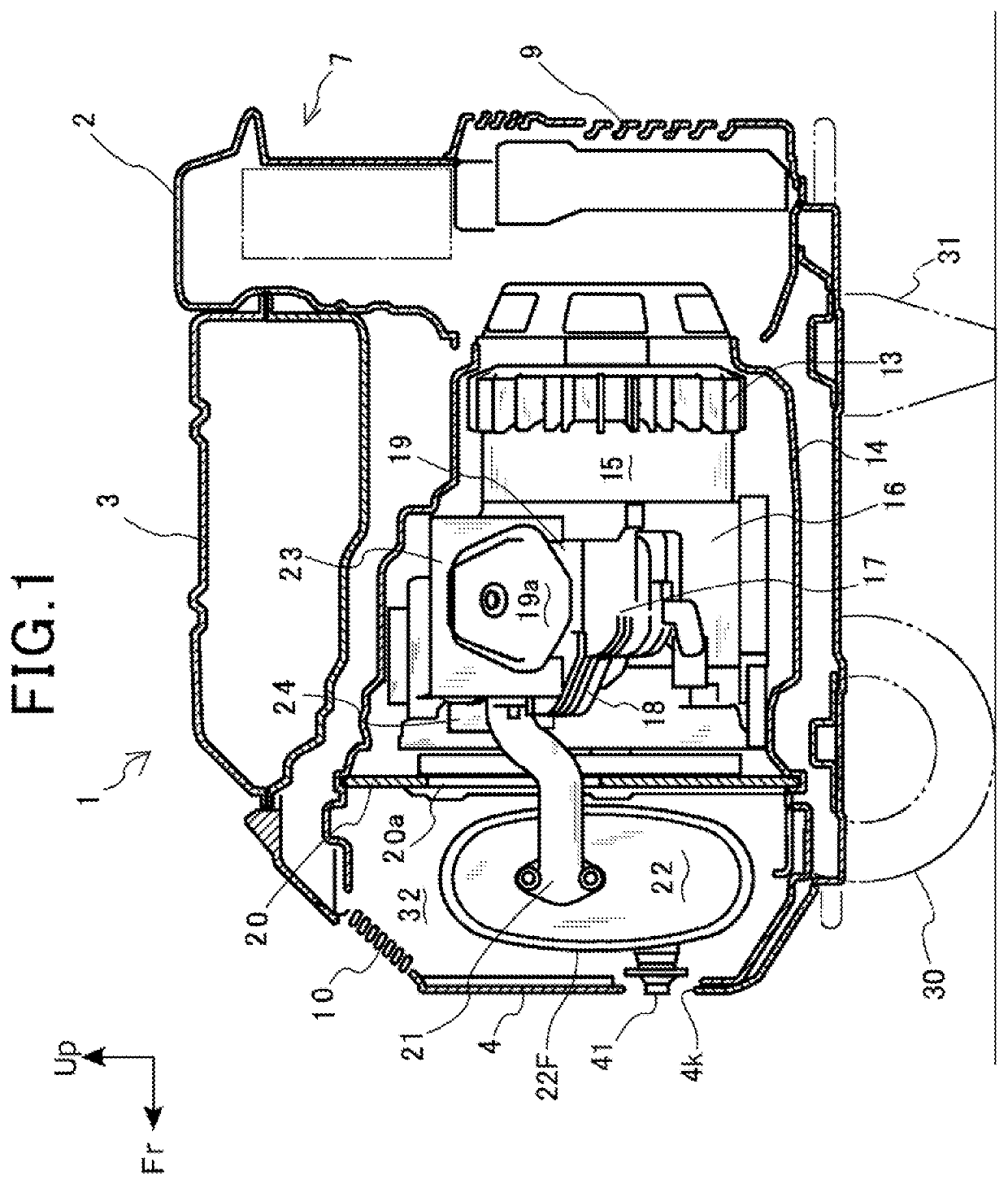
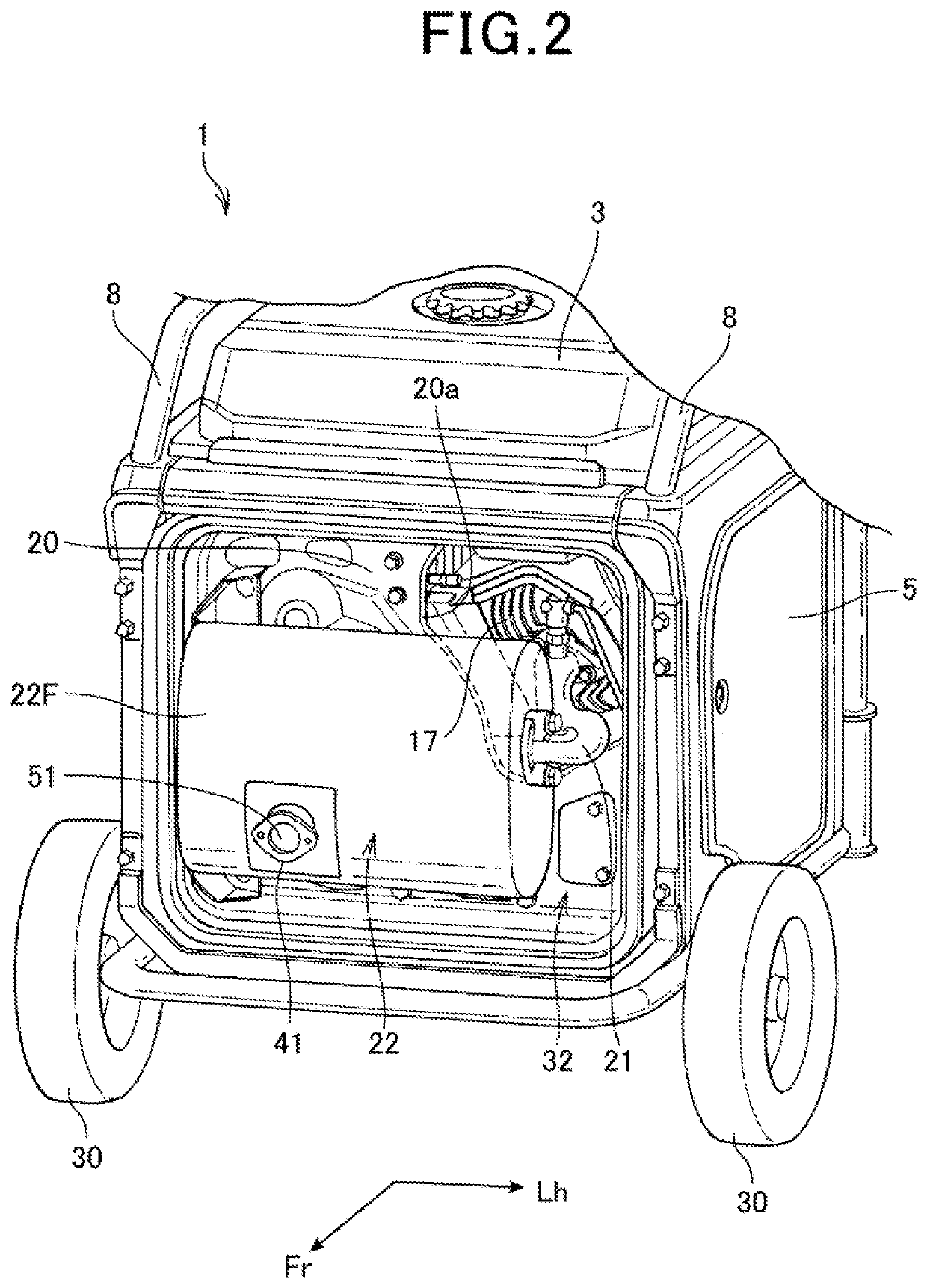
[0028]FIG. 1 is a side sectional view illustrating an internal structure of an engine generator to which an exhaust device according to a first embodiment is applied. FIG. 2 is a perspective view illustrating the exhaust device of the engine generator and peripheral components. In FIGS. 1 and 2, the upward side of the engine generator is indicated by “Up”, the front side of the engine generator is indicated by “Fr”, and the left side of the engine generator is indicated by “Lh”.

[0029]An engine generator 1 includes a housing 2. A fan 13, a generator 15, an engine 16, and an exhaust pipe 21 and a muffler 22, which constitute an exhaust device, are supported in the housing 2.

[0030]As illustrated in FIG. 2, in the housing 2, a front cover 4 (FIG. 1) that covers a front surface of the housing 2 (corresponding to a front surface of the engine generator 1), and a pair of right and left maintenance covers 5 that cover right and left portions of the housing 2 (corresponding to right and left...

second embodiment

[0091]A second embodiment differs from the first embodiment in that the spark arrester 51 is attached to the downstream end of the exhaust pipe 21.

[0092]FIG. 8 is a perspective view of the engine generator 1 to which an exhaust device according to the second embodiment is applied. FIG. 9 is a schematic top view illustrating a connecting section between the tail pipe 41 and the exhaust pipe 21 of the muffler 22. Components similar to those of the first embodiment are denoted by the same reference numerals, and repeated descriptions thereof are omitted.

[0093]As illustrated in FIGS. 8 and 9, the flange part 21F is provided at the downstream end of the exhaust pipe 21. Between the flange part 21F and the muffler 22, a fixing member 81 to be fixed to the flange part 21F with the space 65, which accommodates the flange part 53 of the spark arrester 51, is provided.

[0094]The fixing member 81 includes a tubular main body part 82 through which the net-like main body part 52 of the spark arre...


PUM


Abstract

According to an aspect of the present invention, it is possible to easily support a spark arrester and prevent an occurrence of damage or sound in the spark arrester due to the effect of an exhaust pressure or external vibration. In a spark arrester, at least a flange part is formed of a spring member. The flange part includes a bent part that is telescopically bent by elastic deformation in a direction along a flow of exhaust gas. The bent part is supported between a tail pipe and a muffler in a state where the elastic deformation of the bent part is allowed.

Description

INCORPORATION BY REFERENCE[0001]The present application claims priority under 35 U.S.C. § 119 to Japanese Patent Application No. 2018-045269 filed on Mar. 13, 2018. The content of the application is incorporated herein by reference in its entirety.BACKGROUND OF THE INVENTIONField of the Invention[0002]The present invention relates to an exhaust device equipped with a spark arrester.Description of the Related Art[0003]An exhaust device having a structure in which a spark arrester is attached to an exhaust pipe or a muffler is known.[0004]As support structures for the spark arrester of this type, there are a fastening structure for fastening the spark arrester using bolts, and a nipping structure for nipping the spark arrester between parts. For example, Japanese Utility Model Laid-Open No. H06-76619 discloses a structure in which one end side of a spark arrester is loosely fit to a wall surface of a cylinder, the other end side of the spark arrester engages with a wall portion of a m...

Claims


Application Information

Patent Timeline
Patent Type & Authority Patents(United States)
IPC IPC(8): B01D39/00F01N13/18F01N3/06F04C29/06F01N1/16F01N13/08F01N1/08
CPCF01N13/1844F01N3/06F01N1/08F01N1/16F01N13/082F01N2260/20F01N2290/00F04C29/065Y10S55/20Y10S55/21Y10S181/403Y10S181/404
Inventor TAKADA, HIDEAKITAKADA, SHO
Owner HONDA MOTOR CO LTD
Why Eureka
Try Eureka