Apparatus and method for controlling variable valve mechanism

a technology of variable valve mechanism and valve mechanism, which is applied in the direction of electrical control, non-mechanical valves, machines/engines, etc., can solve problems such as inability to operate, and achieve the effect of reducing o/l and optimum efficiency

Active Publication Date: 2015-08-18
HITACHI ASTEMO LTD
View PDF14 Cites 0 Cited by
  • Summary
  • Abstract
  • Description
  • Claims
  • Application Information

AI Technical Summary

Benefits of technology

[0040]FIG. 2B shows a state of a phase shift where sub cam SC is at the most advanced angle position. The intake valve at this time is brought into an intake valve open timing (IVO) conforming to sub cam SC, and is brought into an intake valve close timing (IVC) conforming to main cam MC, thereby providing a maximum operating angle.
[0069]In these cases, with b1, the open timing IVO of the intake valve on the locking side is retarded, and with b2, the close timing EVC of the exhaust valve on the locking side is retarded. As a result, in both of these cases, O / L is reduced, and hence fuel economy and exhaust emission are deteriorated.
[0074]Consequently, as a fail-safe measure for this case, the variable valve mechanism of the other cam shaft that is not locked, is driven so that the phase of the other cam is retarded and delayed closure control of the intake valve becomes possible.
[0084]For example, FIG. 7B and FIG. 8B are referenced regarding the intake valve. The purpose of advance-controlling main cam MC. (Fr-Valve) and retard-controlling sub cam SC (Rr-Valve) at the same time regarding the IVO according to main cam MC is to increase the overlapping (O / L) with the exhaust valve, and regarding the IVC according to sub cam SC, it is to increase the operating angle with delayed closure.
[0086]Consequently, in this case, there is executed a control such that the phase of sub cam SC (the cam of the other cam shaft) is further retarded, and the intake valve opening area during O / L is reduced while keeping the IVO of the second intake valve from overlapping, to thereby reduce O / L. That is to say, the phase of sub cam SC of inner cam shaft 2 is controlled in the direction of suppressing as much as possible any defect that may occur in the operation of the internal combustion engine due to locking of outer cam shaft 1 (so that the operation approximates the operation at optimum efficiency).

Problems solved by technology

As a result, there is a possibility that a phenomenon of increasing residual gas at the time of idle operation may occur, leading to an undesirable situation such as unstable combustion.

Method used


Image

  • Apparatus and method for controlling variable valve mechanism
  • Apparatus and method for controlling variable valve mechanism
  • Apparatus and method for controlling variable valve mechanism

Examples


Embodiment Construction

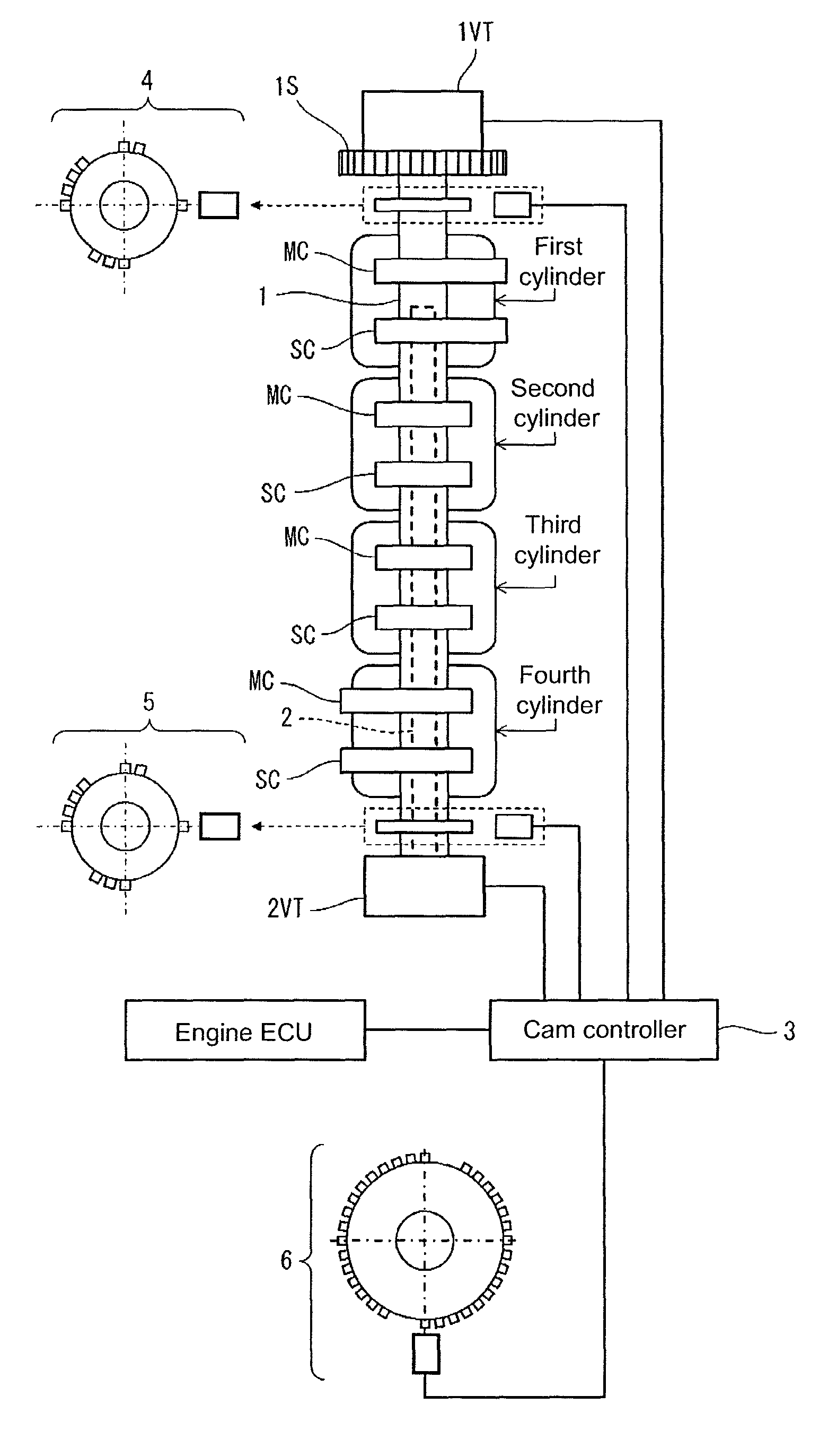
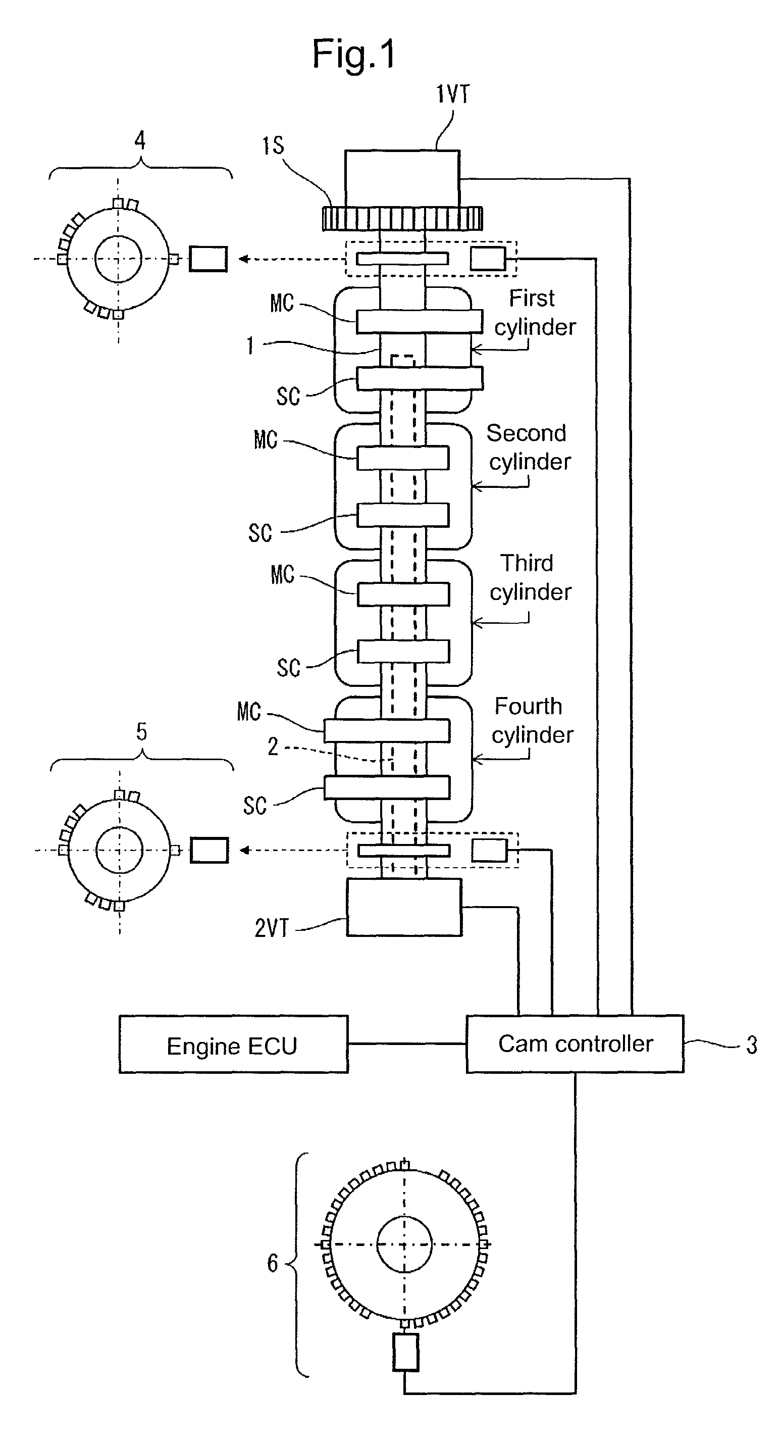
[0026]FIG. 1 shows, as an embodiment, a variable valve mechanism provided on the intake valve side of a DOHC type four-cylinder engine, and a control apparatus thereof. In the case of the present embodiment, on the exhaust valve side there is no variable valve mechanism such as that provided on the intake valve side. However, a similar variable valve mechanism may be provided on the exhaust valve side only, or on both the intake and exhaust valve sides.

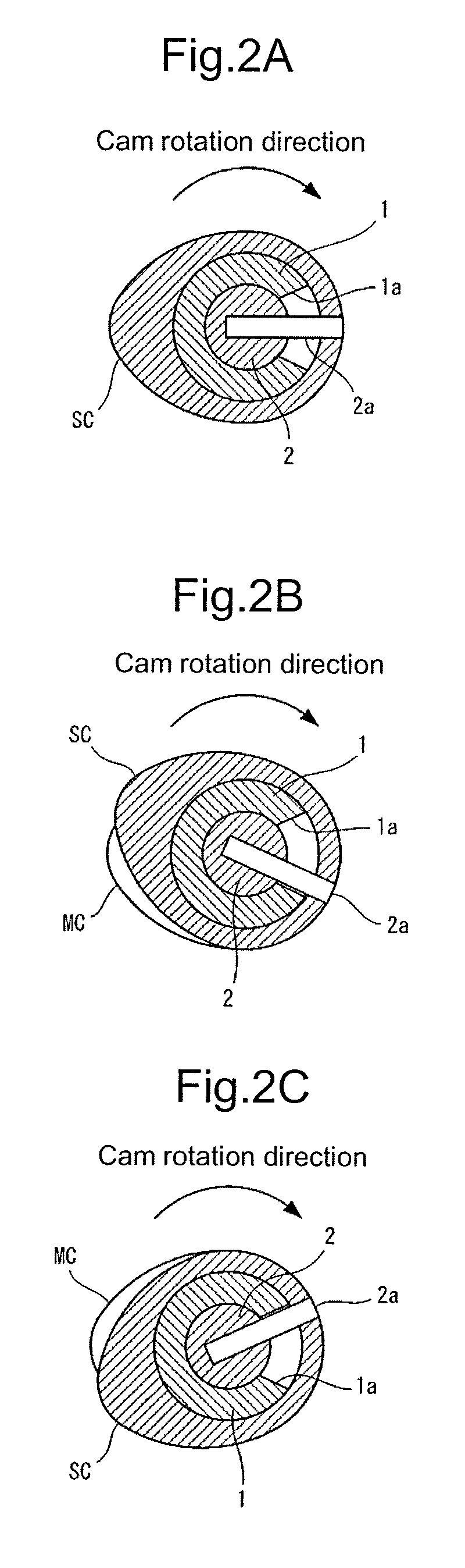
[0027]The variable valve mechanism of the present embodiment has a cam shaft of a double shaft structure having a cylindrical outer cam shaft 1 on the outer side, and an inner cam shaft 2 on the inner side that is inserted into the interior of outer cam shaft 1.

[0028]Outer cam shaft 1 rotates in synchronization with a crank shaft (not shown in the figure) through a timing belt via a sprocket 1S. A main cam MC is attached to this outer cam shaft 1 so as to correspond to each of first to fourth cylinders, to operate a first intake valve...


PUM


Abstract

An control apparatus for a variable valve mechanism, is capable of executing fail safe control in a case in which locking occurs in either one of a cam shaft of a double shaft structure. The control apparatus for a variable valve mechanism has a cam shaft of a double shaft structure including an outer cam shaft and an inner cam shaft, such that it is possible to adjust the phase of a sub cam of inner cam shaft with respect to an main cam of outer cam shaft, and by means these cams, at least one of an intake valve and an exhaust valve of an internal combustion engine is operated. When an abnormality is detected in one of the cam shafts, the control apparatus controls the phase of the cam of the other cam shaft, in accordance with the determined current phase of the cam.

Description

BACKGROUND OF THE INVENTION[0001]1. Field of the Invention[0002]The present invention relates to phase control in a variable valve mechanism of an internal combustion engine.[0003]2. Description of the Related Art[0004]A variable valve mechanism in which a cam shaft that operates an intake valve and an exhaust valve provided for each cylinder, is of a double shaft structure with an outer cam shaft on the outer side and an inner cam shaft on the inner side arranged within this outer cam shaft, and a main cam is attached to the outer cam shaft while a sub cam is attached to the inner cam shaft, is known from the disclosure of Japanese Laid-open (Kokai) Patent Publication Application No. 2002-054410 (Patent Document 1) and Japanese Laid-open (Kokai) Patent Publication Application No. 2009-144521 (Patent Document 2). This type of variable valve mechanism is provided on either one or both of an intake valve and an exhaust valve, and the phase of a cam is appropriately changed to thereby ...

Claims


Application Information

Patent Timeline
Patent Type & Authority Patents(United States)
IPC IPC(8): F02D41/22F01L9/04F01L1/34F01L1/047
CPCF01L1/34F01L2001/0473F01L2250/04F01L2800/12
Inventor ARAYA, NORIHIROMACHIDA, KENICHI
Owner HITACHI ASTEMO LTD
Why Eureka
Try Eureka