Modular battery structure

a module and battery technology, applied in the direction of cell components, electrical equipment, cooling/ventilation/heating modification, etc., can solve the problems of increasing the cost of individual module replacement, permanently damaging the energy storage device, and having a negative effect on the function and performance of the energy storage devi

Inactive Publication Date: 2015-08-18
ARKISS IP UG HAFTUNGSBESCHRANKT
View PDF18 Cites 3 Cited by
  • Summary
  • Abstract
  • Description
  • Claims
  • Application Information

AI Technical Summary

Benefits of technology

[0013]In an embodiment, it is proposed to provide an integration of all key functions at a cell module level, thus cooling and thermal and electrical contacting. A fundamental idea is the development of a standard module with a low adaptation cost for alternative cell sizes and with high quantities. Important key points in this regard are a high modularity, very rapid and simple replaceability of cell modules in the event of damage, and advantageous production owing to the high standardization and low application cost.
[0014]The present invention is based on the realization that because of a considerable increase in the degree of modularization of accumulator and cooling systems, a system can be created that is based on a small, uniform assembly group, which already comprises, for example, all relevant interfaces, particularly an electrical, a mechanical, and a thermal interface. This unit can be expanded as desired and adapted at very low cost to the specific application. In addition, a more economic and cost-effective fabrication and development can be achieved owing to the higher quantities resulting therefrom.
[0015]The above-described object of the invention can be attained by a more or less small base unit. The base unit has an assembly group, which contains one or more energy storage devices and the necessary interfaces. In this case, the electrical, mechanical, and thermal interfaces can already be integrated into said base unit. Said base unit in turn can be integrated into a base frame, which can accommodate one or more base units and be expanded as desired according to the specific application. The invention represents a novel design of battery systems for hybrid and electrical applications with a high modularity as an alternative to conventional structural designs.
[0016]A battery system with a relatively small installation space and weight can be realized with the concept of the invention. This type of system is also characterized by a high flexibility relative to the design. According to the inventive approach, identical elements can be produced in large quantities, whereby a greater economy of the production can be achieved. A modular accumulator and cooling system according to the inventive approach enables a lower application effort for the individual application and thereby shorter development times. The introduction and transmission of force and a tolerance compensation in the energy storage units are advantageously combined in a single concept. Finally, an accumulator and cooling system, produced and used according to the inventive approach, is characterized by a substantially greater maintenance and service friendliness.
[0018]The cell modules represent only a mechanical connection of the cells. Cell connector boards and cooling plates can be retained during the replacement of individual modules. In the case of damage, this reduces the cost of the battery replacement considerably, because only individual modules need to be replaced, and a new connection of cooling channels is not necessary. Specific batteries can be assembled from identical cell modules depending on (performance) requirements.
[0022]According to another embodiment, the support-side cooling fluid connection may have a flange. This enables an easy-to-use and nevertheless fluid-tight connection between the module and support.

Problems solved by technology

Temperatures above 50° C. damage the energy storage devices permanently.
With a nonuniform cooling of the cells, the cells age at a different rate, and this has a negative effect on the function and performance of the energy storage devices.
This increases the cost for the replacement of individual modules considerably and harbors the risk of leaks.
The state of the art is based very heavily on accumulator and cooling systems that are adapted to the particular application and whose development and production is very complicated and costly, inter alia, because of the thus far still relatively low quantities.

Method used


Image

  • Modular battery structure
  • Modular battery structure
  • Modular battery structure

Examples


Embodiment Construction

[0044]In the following description of the preferred exemplary embodiments of the present invention, the same or similar reference symbols are used for the elements with a similar action and shown in the different drawings, whereby a repeated description of these elements is omitted.

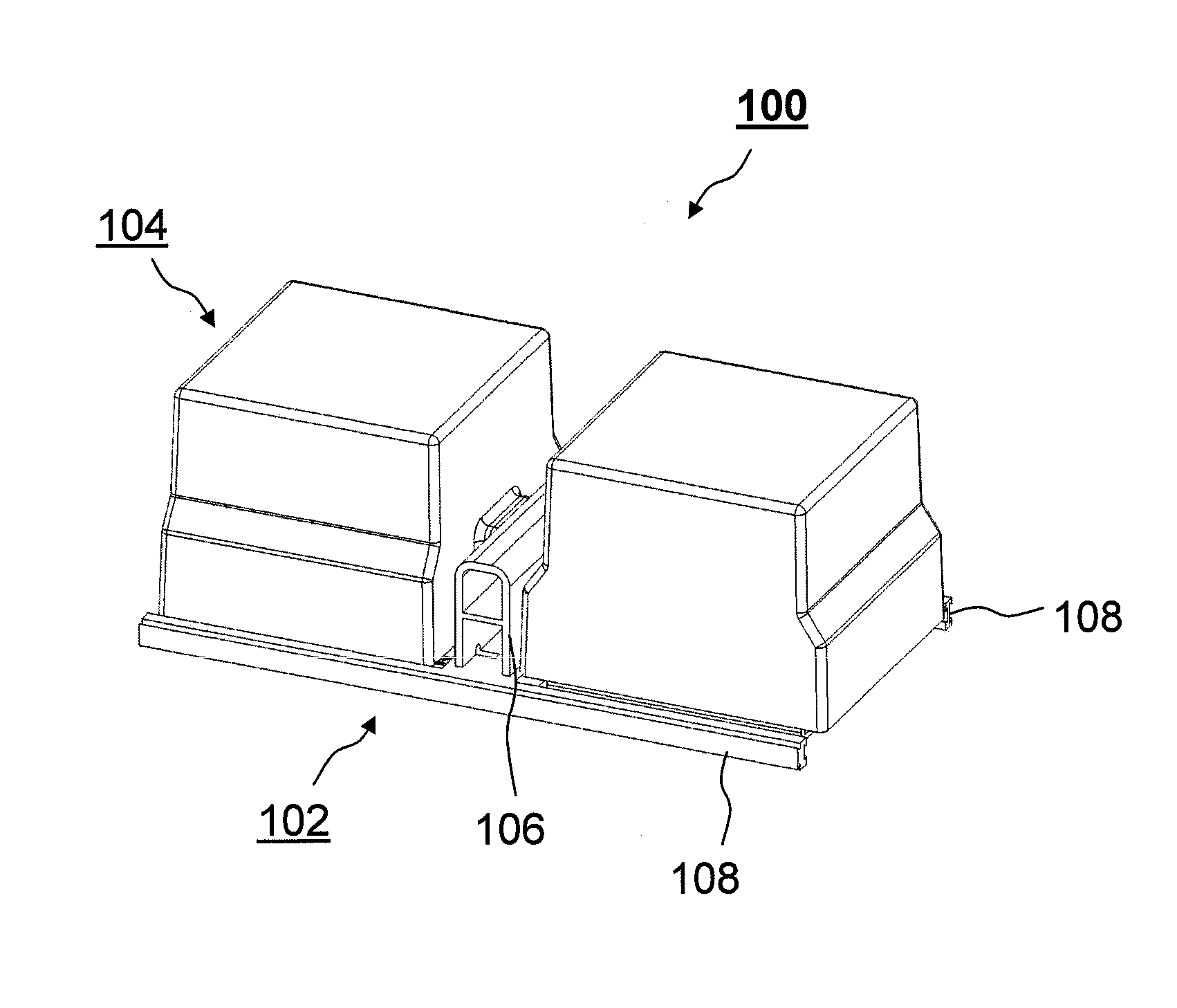
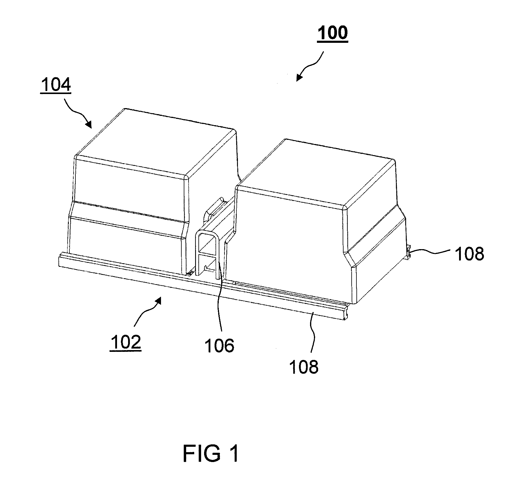
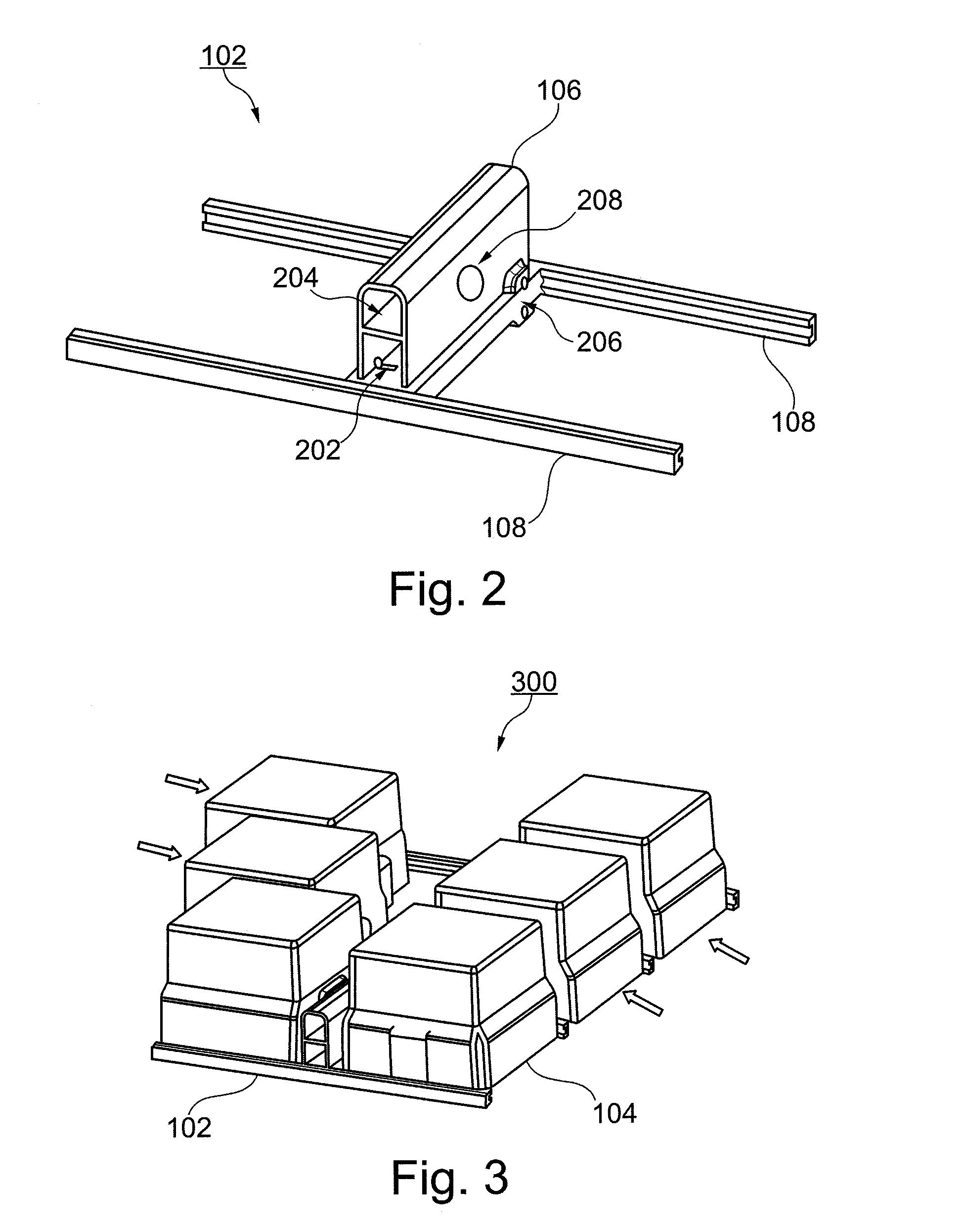
[0045]FIG. 1 shows a perspective view of a modular system 100 according to an exemplary embodiment of the invention. Shown is a module support 102, which supports two energy storage modules 104. Module support 102 has a support housing 106 with two opposite side walls and two rails 108, which are arranged in each case approximately at right angles to support housing 106 and in each case extend in opposite directions away from support housing 106. Each of energy storage modules 104 is arranged adjacent to one of the side walls of support housing 106. Energy storage modules 104 can be connected to module support 102 by insertion into rails 108, in each case from opposite directions.

[0046]FIG. 2 shows a pers...


PUM

PropertyMeasurementUnit
resistancesaaaaaaaaaa
forcesaaaaaaaaaa
sizesaaaaaaaaaa

Abstract

A module system is provided that includes at least one module support and at least one module support and at least one energy storage module that is connected to the at least one module support. The module support and the energy storage module have cooling fluid connections, electric contacts, and coupling elements that are adapted to each other.

Description

[0001]This nonprovisional application is a continuation of International Application No. PCT / EP2010 / 063057, which was filed on Sep. 6, 2010, and which claims priority to German Patent Application No. DE 10 2009 040 197.0, which was filed in Germany on Sep. 7, 2009, and which are both herein incorporated by reference.BACKGROUND OF THE INVENTION[0002]1. Field of the Invention[0003]The present invention relates to a module support for a modular system, an energy storage module for a modular system, and a modular system.[0004]2. Description of the Background Art[0005]High-performance energy storage devices such as, for example, Li-ion or NiMH accumulators or supercaps are used in modern HEV / EV vehicles. Heating occurs in these during rapid charging and discharging due to resistances within and outside the cells. Temperatures above 50° C. damage the energy storage devices permanently. To assure the function of the energy storage devices, they must be cooled. To this end, the energy stora...

Claims


Application Information

Patent Timeline
Patent Type & Authority Patents(United States)
IPC IPC(8): H01M10/00H05K7/20H01M2/10H01M10/656H01M10/613H01M10/6556H01M10/625H01M10/6566H01M10/6557H01M10/647H01M50/204
CPCH01M2/1083H01M2/1077H01M10/613H01M10/625H01M10/656H01M10/6556H01M10/647H01M10/6557H01M10/6566Y02E60/10H01M50/204H01M10/6568
Inventor KOHLBERGER, MARKUSMOSER, MICHAELNEFF, HEIKOSCHMID, CAROLINEHERRMANN, HANS-GEORG
Owner ARKISS IP UG HAFTUNGSBESCHRANKT
Why Eureka
Try Eureka