Modular battery structure

Active Publication Date: 2012-09-06
ARKISS IP UG HAFTUNGSBESCHRANKT
View PDF2 Cites 34 Cited by
  • Summary
  • Abstract
  • Description
  • Claims
  • Application Information

AI Technical Summary

Benefits of technology

[0012]It is therefore an object of the present invention provide an

Problems solved by technology

Temperatures above 50° C. damage the energy storage devices permanently.
With a nonuniform cooling of the cells, the cells age at a different rate, and this has a negative effect on the function and performance of the energy storage devices.
This increases the cost for the replacement of individual modules

Method used


Image

  • Modular battery structure
  • Modular battery structure
  • Modular battery structure

Examples


Embodiment Construction

[0044]In the following description of the preferred exemplary embodiments of the present invention, the same or similar reference symbols are used for the elements with a similar action and shown in the different drawings, whereby a repeated description of these elements is omitted.

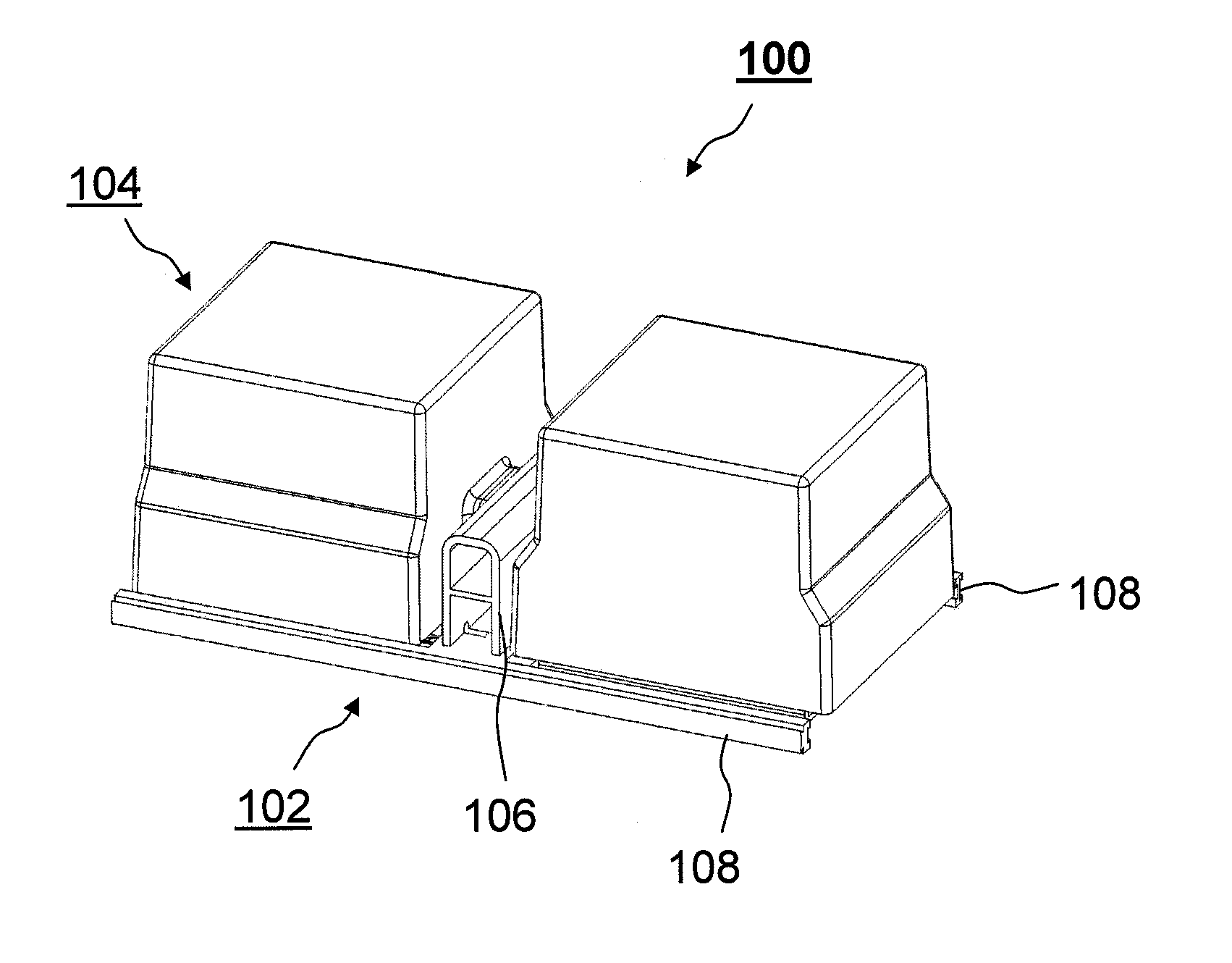
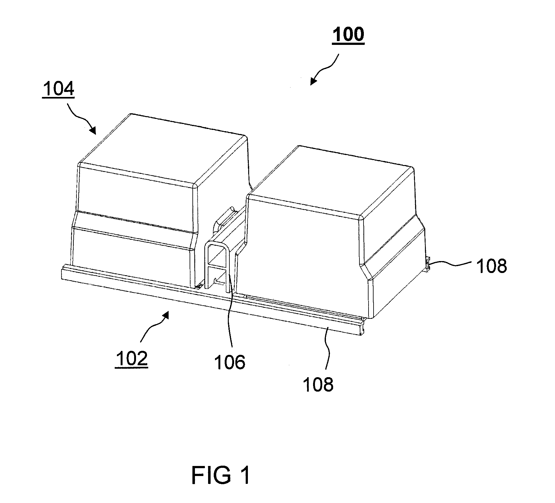
[0045]FIG. 1 shows a perspective view of a modular system 100 according to an exemplary embodiment of the invention. Shown is a module support 102, which supports two energy storage modules 104. Module support 102 has a support housing 106 with two opposite side walls and two rails 108, which are arranged in each case approximately at right angles to support housing 106 and in each case extend in opposite directions away from support housing 106. Each of energy storage modules 104 is arranged adjacent to one of the side walls of support housing 106. Energy storage modules 104 can be connected to module support 102 by insertion into rails 108, in each case from opposite directions.

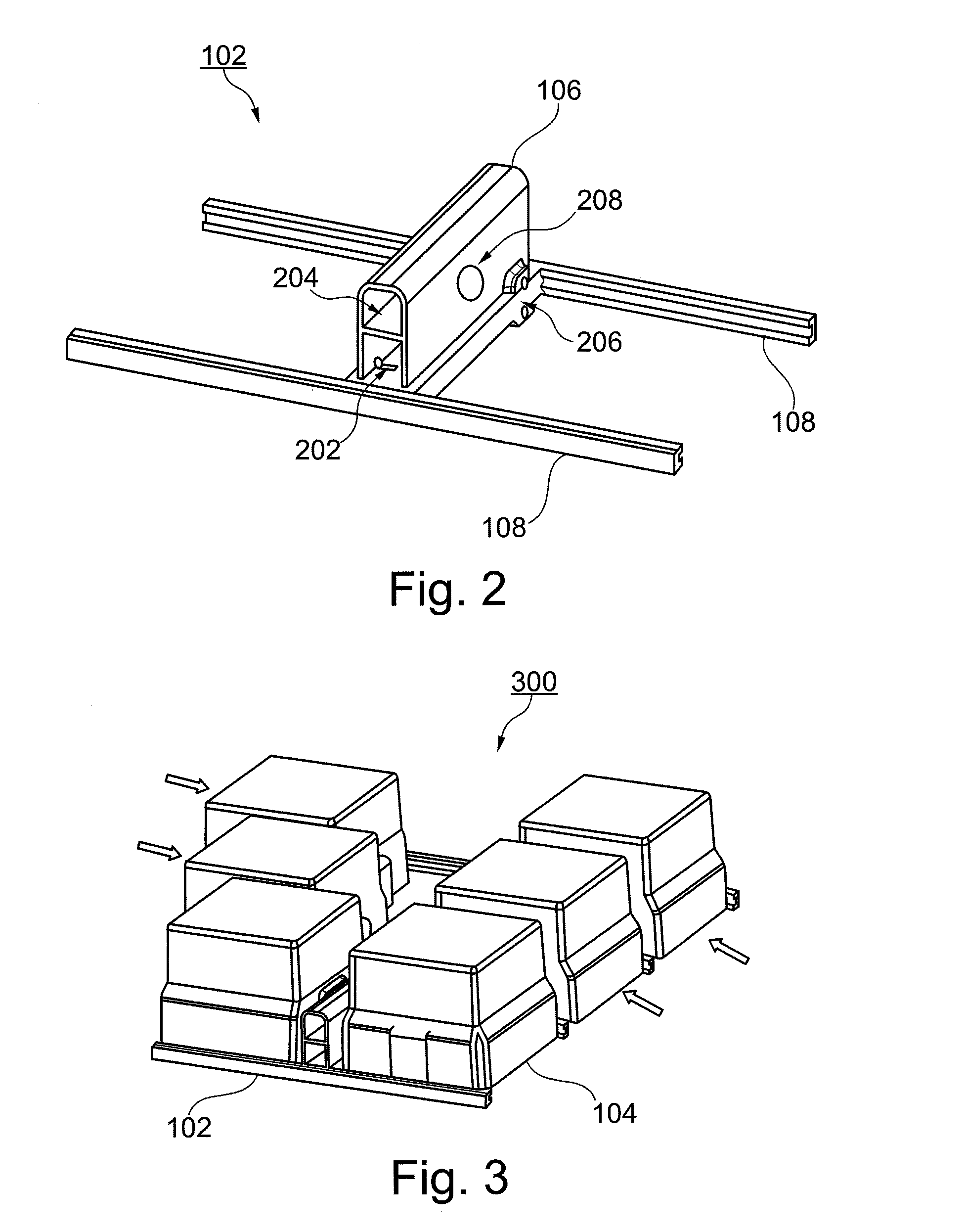
[0046]FIG. 2 shows a pers...


PUM


Abstract

A module system is provided that includes at least one module support and at least one module support and at least one energy storage module that is connected to the at least one module support. The module support and the energy storage module have cooling fluid connections, electric contacts, and coupling elements that are adapted to each other.

Description

[0001]This nonprovisional application is a continuation of International Application No. PCT / EP2010 / 063057, which was filed on Sep. 6, 2010, and which claims priority to German Patent Application No. DE 10 2009 040 197.0, which was filed in Germany on Sep. 7, 2009, and which are both herein incorporated by reference.BACKGROUND OF THE INVENTION[0002]1. Field of the Invention[0003]The present invention relates to a module support for a modular system, an energy storage module for a modular system, and a modular system.[0004]2. Description of the Background Art[0005]High-performance energy storage devices such as, for example, Li-ion or NiMH accumulators or supercaps are used in modern HEV / EV vehicles. Heating occurs in these during rapid charging and discharging due to resistances within and outside the cells. Temperatures above 50° C. damage the energy storage devices permanently. To assure the function of the energy storage devices, they must be cooled. To this end, the energy stora...

Claims


Application Information

Patent Timeline
IPC IPC(8): H05K7/20H01M50/204
CPCH01M2/1077H01M2/1083H01M10/5004H01M10/5016H01M10/5073H01M10/5057H01M10/5059H01M10/5061H01M10/5032H01M10/625H01M10/647H01M10/6556H01M10/6557H01M10/6566H01M10/613H01M10/656Y02E60/10H01M50/204H01M10/6568
Inventor KOHLBERGER, MARKUSMOSER, MICHAELNEFF, HEIKOSCHMID, CAROLINEHERRMANN, HANS-GEORG
Owner ARKISS IP UG HAFTUNGSBESCHRANKT
Why Eureka
Try Eureka