
Power outlet cameras

a technology of power outlet and camera, which is applied in the direction of substation equipment, television systems, instruments, etc., can solve the problems of inability to connect to the first wireless network, high cost and time-consuming of installing video cameras inside buildings,

Active Publication Date: 2015-08-18
SKYBELL TECH IP LLC
View PDF154 Cites 307 Cited by
  • Summary
  • Abstract
  • Description
  • Claims
  • Application Information

AI Technical Summary

Benefits of technology

The patent describes a system that can detect and track people in a building using a power outlet and a security system. The system can also analyze images to accurately track the person's movement. The technical effect is that the system can provide a better way to secure buildings and prevent unauthorized access.

Problems solved by technology

Installing videos cameras inside of buildings can be expensive and time consuming.
Although some security systems are installed to function as doorbells, other security systems do not function as doorbells and might not even include a doorbell button.
If the computing device is outside the wireless range, then the computing device cannot connect to the first wireless network.

Method used


Image

  • Power outlet cameras
  • Power outlet cameras
  • Power outlet cameras

Examples


Embodiment Construction

[0297]Although certain embodiments and examples are disclosed below, inventive subject matter extends beyond the specifically disclosed embodiments to other alternative embodiments and / or uses, and to modifications and equivalents thereof. Thus, the scope of the claims appended hereto is not limited by any of the particular embodiments described below. For example, in any method or process disclosed herein, the acts or operations of the method or process may be performed in any suitable sequence and are not necessarily limited to any particular disclosed sequence. Various operations may be described as multiple discrete operations in turn, in a manner that may be helpful in understanding certain embodiments; however, the order of description should not be construed to imply that these operations are order dependent. Additionally, the structures, systems, and / or devices described herein may be embodied as integrated components or as separate components.

[0298]For purposes of comparing...


PUM


Abstract

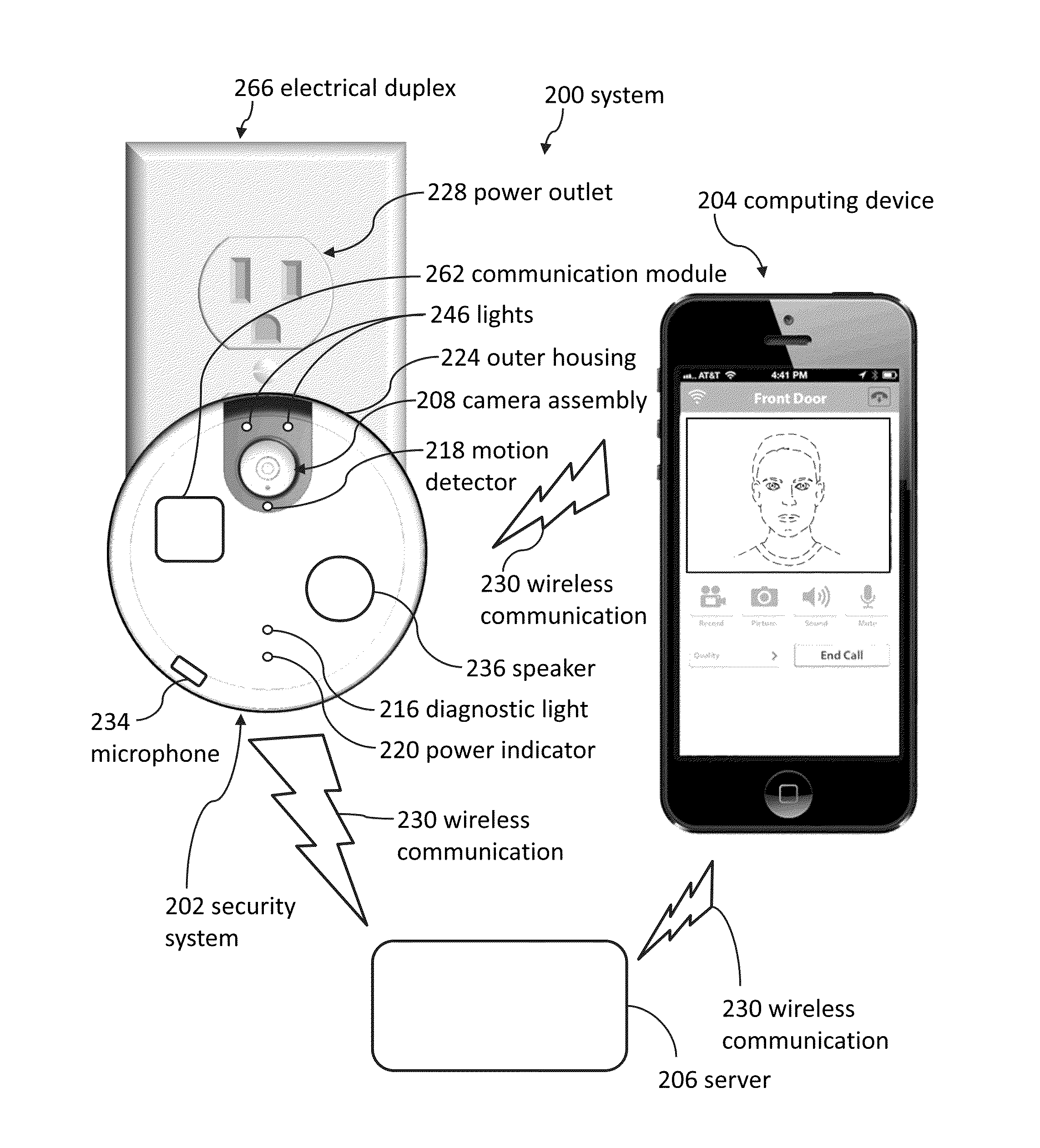
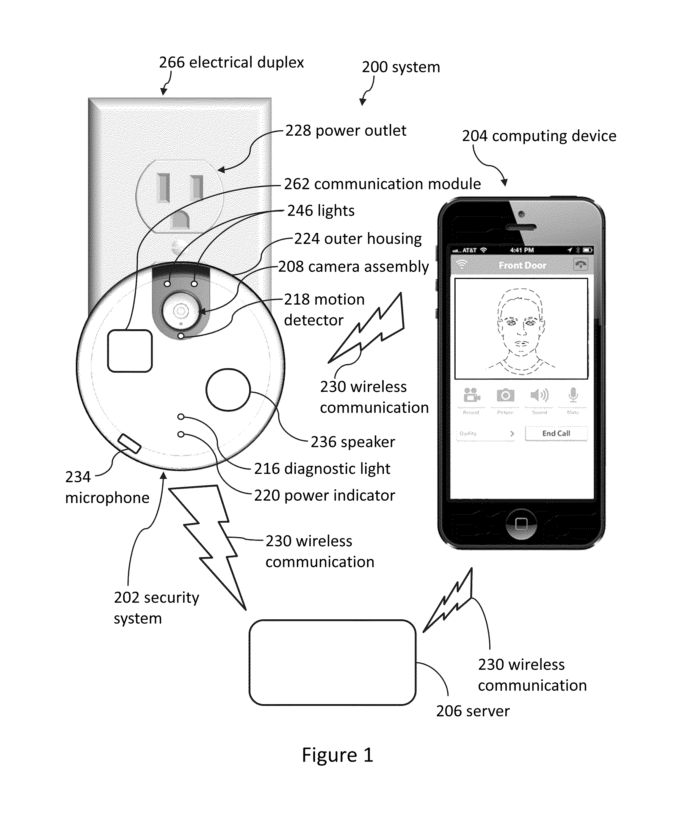
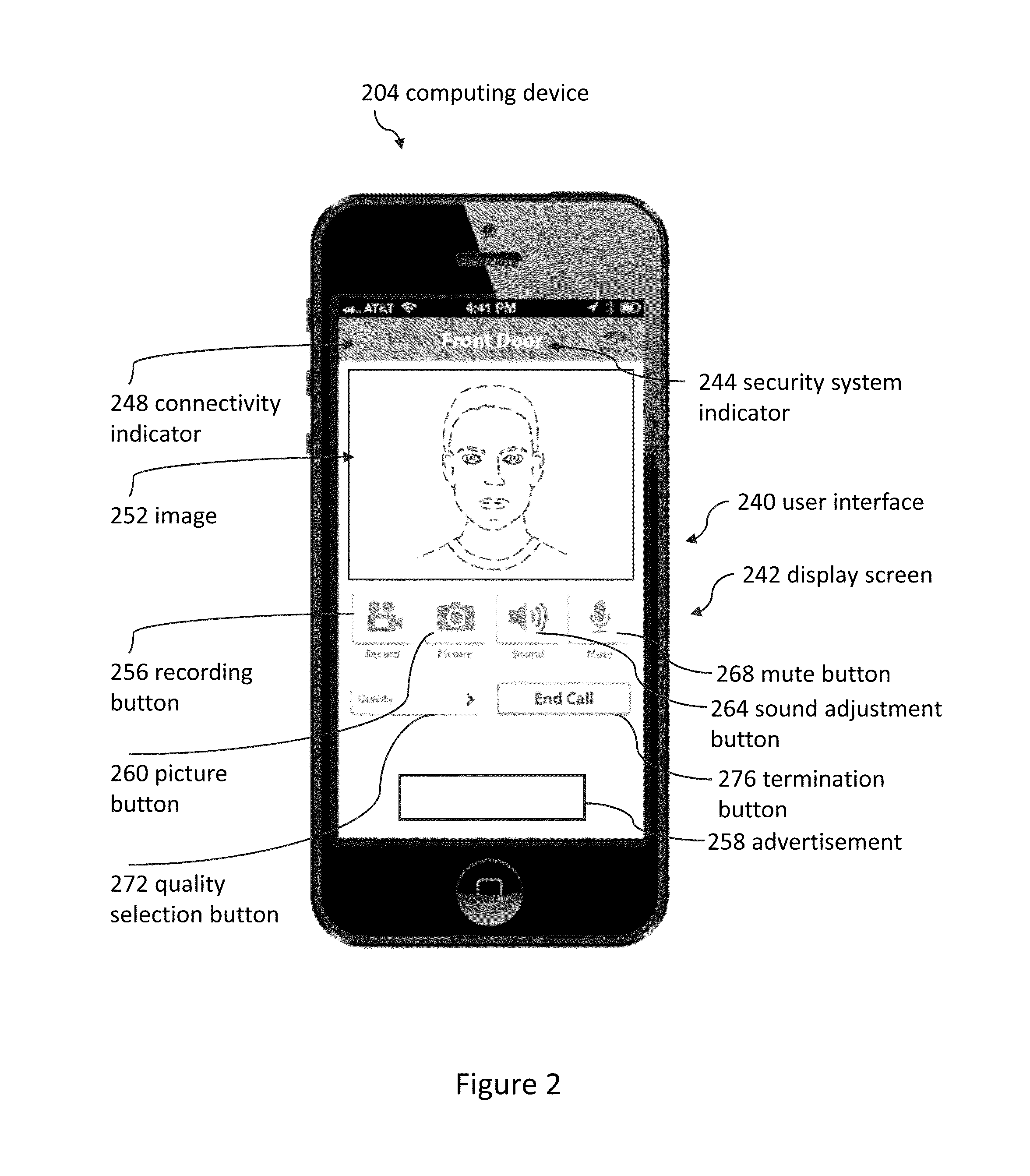
Remote surveillance systems can include an outward portion that faces away from a power outlet and can include an inward portion with electrical prongs that protrude into the power outlet. The power outlet can mechanically support the inward portion and a camera assembly. The remote surveillance system can take videos using the camera and can send the videos to a remotely located computing device.

Description

CROSS-REFERENCE TO RELATED APPLICATIONS[0001]This application claims the benefit of U.S. Provisional Patent Application No. 62 / 016,863; filed Jun. 25, 2014; and entitled WALL PLUG CAMERAS. The entire contents of Patent Application No. 62 / 016,863 are incorporated by reference herein.[0002]The entire contents of the following application are incorporated by reference herein: U.S. Design patent application No. 29 / 497,747; filed Jul. 28, 2014; and entitled POWER OUTLET CAMERA.[0003]The entire contents of the following applications are incorporated by reference herein: U.S. Nonprovisional patent application Ser. No. 14 / 612,376; filed Feb. 3, 2015; and entitled DOORBELL COMMUNICATION SYSTEMS AND METHODS; U.S. Nonprovisional patent application Ser. No. 14 / 589,830; filed Jan. 5, 2015; and entitled DOORBELL COMMUNICATION SYSTEMS AND METHODS; U.S. Nonprovisional patent application Ser. No. 14 / 502,601; filed Sep. 30, 2014; and entitled DOORBELL COMMUNICATION SYSTEMS AND METHODS; U.S. Nonprovis...

Claims


Application Information

Patent Timeline
Patent Type & Authority Patents(United States)
IPC IPC(8): H04N7/18H04N9/47
CPCH04N7/185H04N7/186H04N7/188G08B13/19684H04M1/0291H04M11/025H04M1/72412H04M1/72418
Inventor SCALISI, JOSEPH FRANK
Owner SKYBELL TECH IP LLC
Learn More