Unlock instant, AI-driven research and patent intelligence for your innovation.

Display device with gray scale data correction

a technology of gray scale data and display device, which is applied in the field of display device, can solve the problems of reducing the contrast of images of certain types, difficulty in viewing images by viewers, etc., and achieves the effect of reducing crosstalk and minimizing the reduction of image contras

Inactive Publication Date: 2015-08-18
SHARP KK
View PDF15 Cites 0 Cited by
  • Summary
  • Abstract
  • Description
  • Claims
  • Application Information

AI Technical Summary

Benefits of technology

The technical effect of this patent is to create a display device that reduces crosstalk while maintaining the intensity of images.

Problems solved by technology

This makes it difficult to view the image that the viewer is supposed to view.
While approaches described in the above publications may reduce crosstalk, they may decrease the contrast of images of certain types.

Method used


Image

  • Display device with gray scale data correction
  • Display device with gray scale data correction
  • Display device with gray scale data correction

Examples


first embodiment

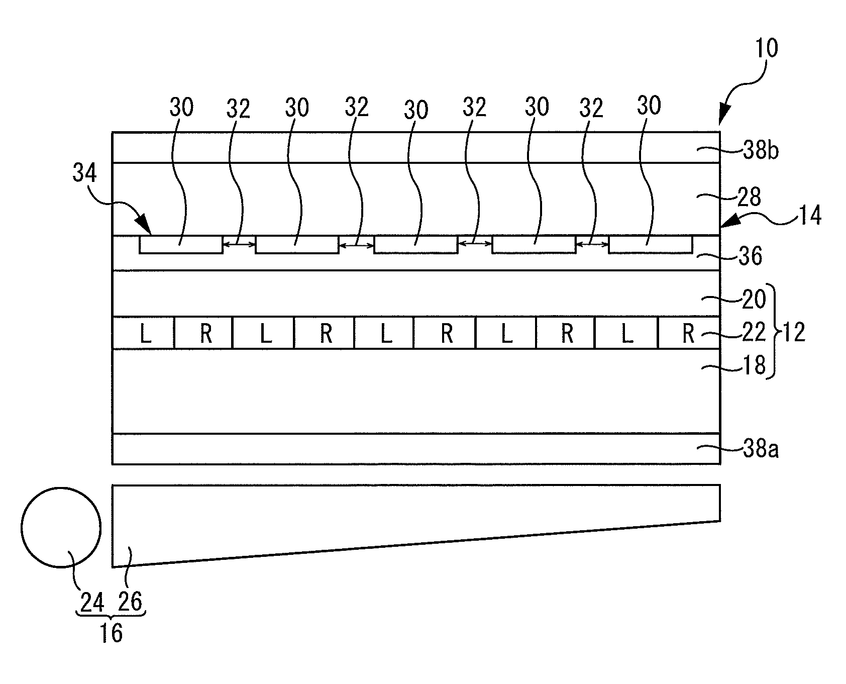
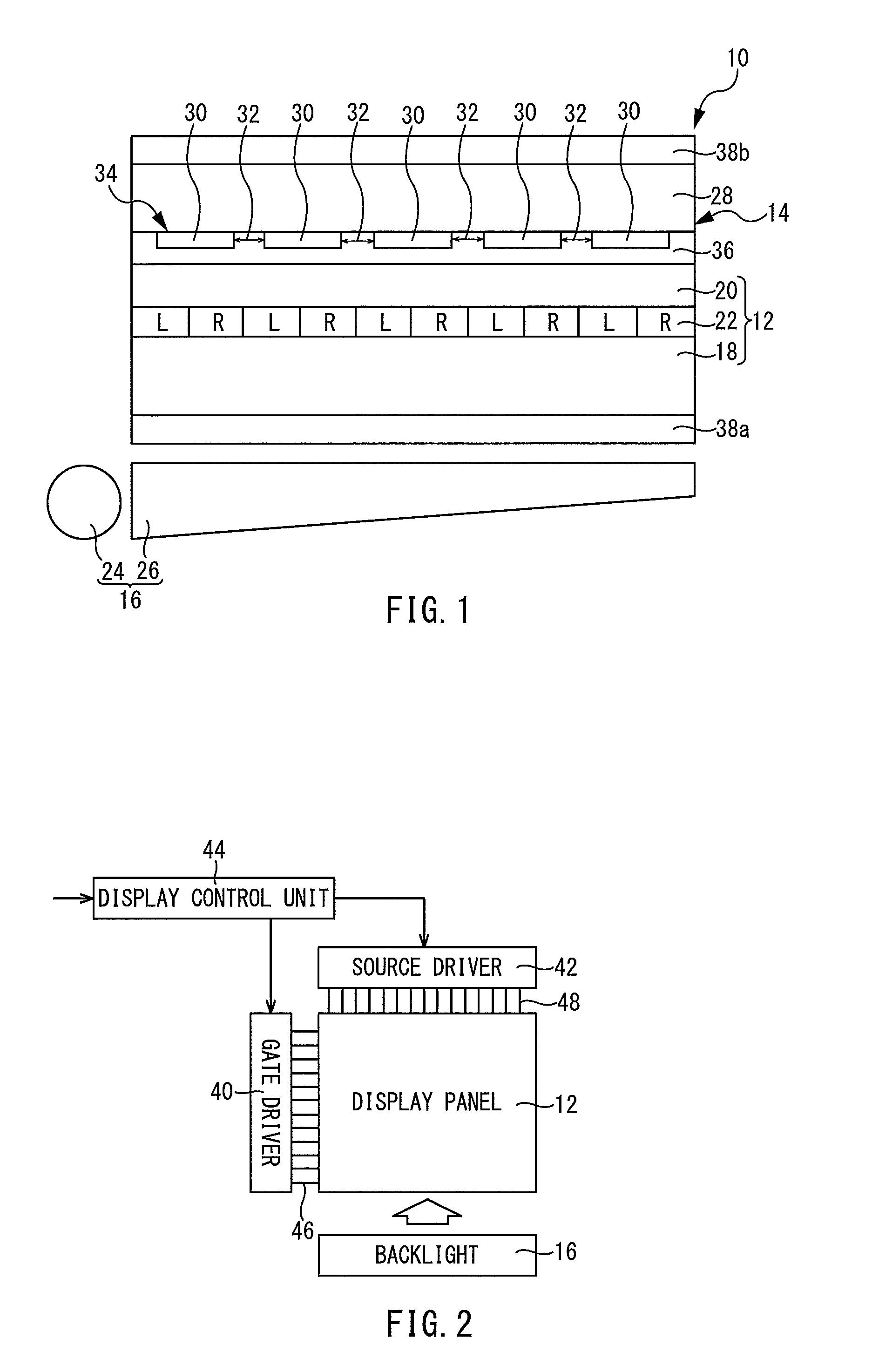
[0052]FIG. 1 shows a display device 10 of a first embodiment of the present invention. The display device 10 includes a display panel 12, a barrier unit 14 and a backlight 16.

[0053]The display panel 12 is a liquid crystal panel. Briefly, the display panel 12 includes an active-matrix substrate 18 having a plurality of pixel electrodes arranged in a matrix, a counter substrate 20 having a common electrode formed thereon, and a liquid crystal layer 22 enclosed between the active-matrix substrate 18 and counter substrate 20. Pixels that include the pixel electrodes are formed. The region where a plurality of pixels are arranged in a matrix constitutes the display region of the display panel 12. In the present embodiment, as shown in FIG. 1, rows of pixels R for displaying right eye images and rows of pixels L for displaying left eye images are arranged in an alternating manner.

[0054]In other words, in the present embodiment, right eye images and left eye images are divided into stripes...

application example 1 of first embodiment

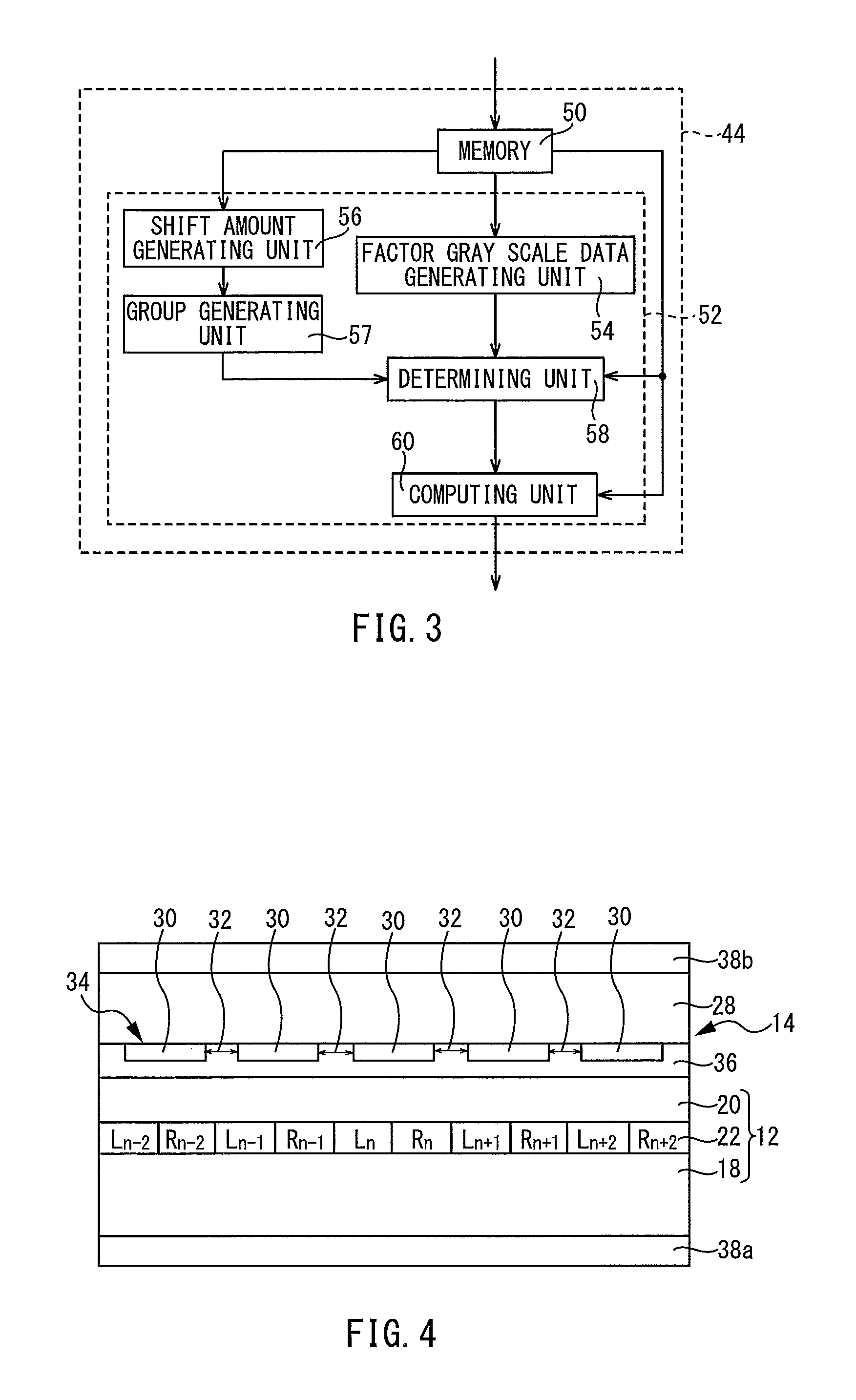
[0134]In the present application example, the factor gray scale data I′RN used to correct crosstalk for the pixel Ln shown in FIG. 4 may be calculated by the following Equation (21):

I′Rn=An-1×IRn−1+An×IRn  (21),

where An-1 is the rate of contribution of the pixel Rn-1 to crosstalk. An is the rate of contribution of the pixel Rn to crosstalk. An-1 and An are in the range from 0 to 1.

[0135]An-1 and An vary for each display device depending on, for example, the distance between two adjacent light-shielding layers 30 in the parallax barrier 34, the shape of the light-shielding layers 30, the material of the light-shielding layers 30, the locations of the light-shielding layers 30, the width of the light-shielding layers 30, the thickness of the light-shielding layers 30, and the positional relationship between the light-shielding layers 30 and the pixels R and L. An-1 and An may be obtained by measurements for each display device. These values may be obtained by, for example, measuring t...

application example 2 of first embodiment

[0138]In the present application example, the barrier unit 14 is replaced by a lenticular lens 72 that serves as the separating unit, as shown in FIG. 7. The lenticular lens 72 includes a plurality of cylindrical lenses 74 aligned with rows of pixels R and rows of pixels L arranged in an alternating manner. The lenticular lens 72 is attached to the polarizer 38b adjacent the counter substrate 20 such that each cylindrical lens 74 corresponds to a row of pixels R or L. In the present application example, the polarizer 38b located adjacent the counter substrate 20 is attached to the counter substrate 20.


PUM


Abstract

The display device includes: a display unit configured to display a combined image formed by dividing a plurality of different images into divided images and arranging the divided images in a predetermined order; a separating unit configured to separate the plurality of images included in the combined image; and a correcting unit configured to correct the gray scale data of a pixel that displays one of the plurality of images included in the combined image that the viewer is supposed to see, wherein the correcting unit includes: a shift amount generating unit configured to generate a shift amount used to adjust the gray scale data of each pixel that displays one of the plurality of images included in the combined image; and a determining unit configured to determine a correction amount used to correct the gray scale data using the shift amount generated by the shift amount generating unit.

Description

RELATED APPLICATIONS[0001]The present application is a National Phase of International Application Number PCT / JP2012 / 054303, filed Feb. 22, 2012, and claims priority from Japanese Application Number 2011-040287, filed Feb. 25, 2011.TECHNICAL FIELD[0002]The present invention relates to display devices where crosstalk can be reduced.BACKGROUND ART[0003]Recently, display devices have been proposed that use a parallax barrier to separate a plurality of images included in a combined image displayed on the display panel to allow them to be viewed from different directions. Examples include the display devices described in WO 2007-32132 and JP 2004-312780 A. These display devices are commercialized as, for example, stereoscopic displays in digital cameras, dual-view display devices mounted on vehicles, and the like.[0004]However, when a viewer sees one of a plurality of images on such display devices, he may see another image as well (crosstalk). This makes it difficult to view the image t...

Claims


Application Information

Patent Timeline
Patent Type & Authority Patents(United States)
IPC IPC(8): G09G5/10H04N13/04G02B27/22H04N13/00G09G3/00G02B30/26G02B30/27G02B30/30
CPCH04N13/0404G02B27/225H04N13/007H04N13/04H04N13/0409G09G3/003H04N13/106H04N13/183H04N13/305H04N13/31H04N13/30G02B30/27G02B30/30G02B30/26
Inventor SONE, TAKUYATANAKA, NORIYUKI
Owner SHARP KK