
Steering for independent suspension system

a steering system and independent technology, applied in the direction of suspensions, resilient suspensions, vehicle components, etc., can solve the problem that the suspension system lacks a means of controlling the directional orientation of the knuckles

Inactive Publication Date: 2015-08-25
BANDY RONALD SCOTT
View PDF16 Cites 16 Cited by
  • Summary
  • Abstract
  • Description
  • Claims
  • Application Information

AI Technical Summary

Benefits of technology

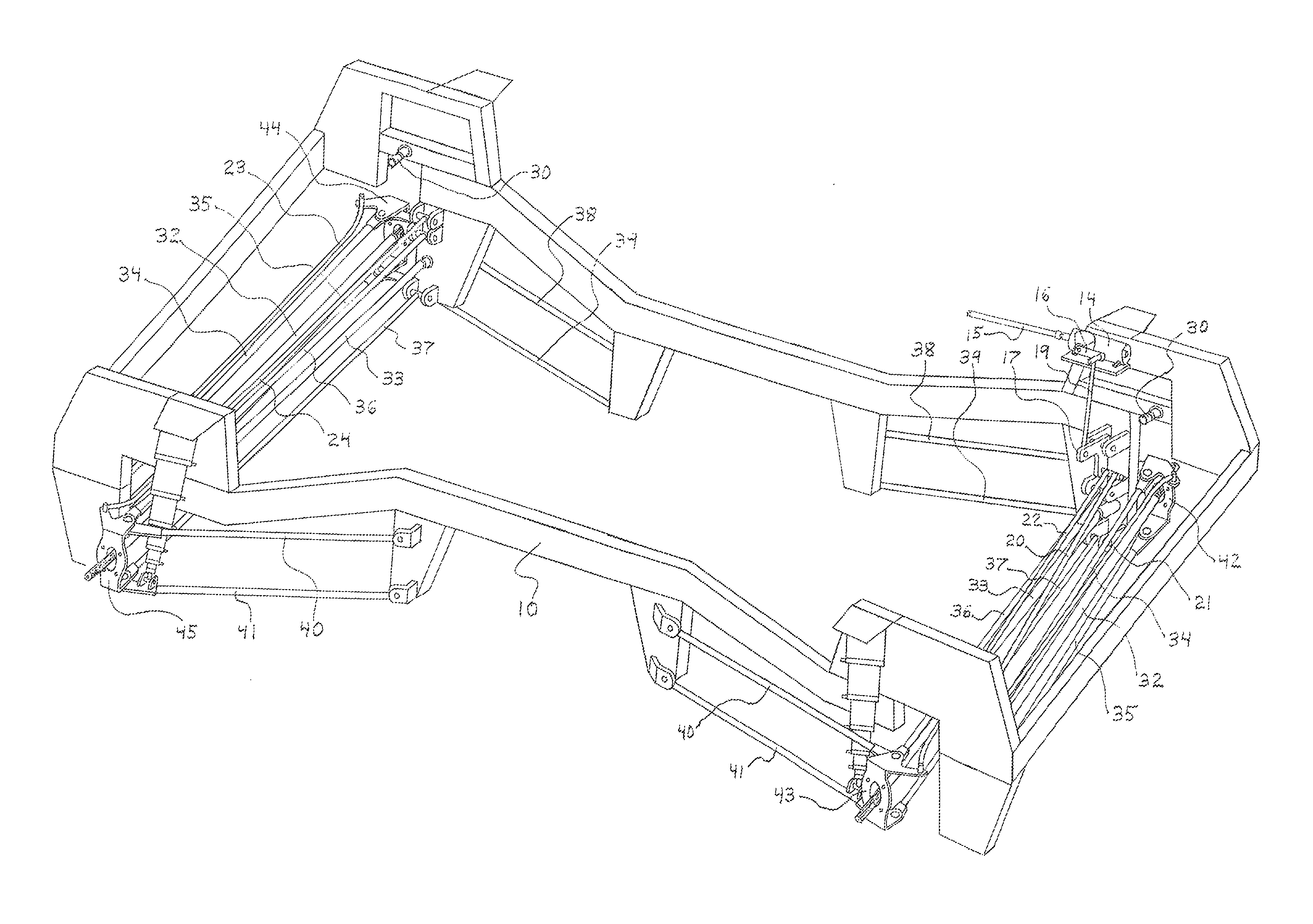
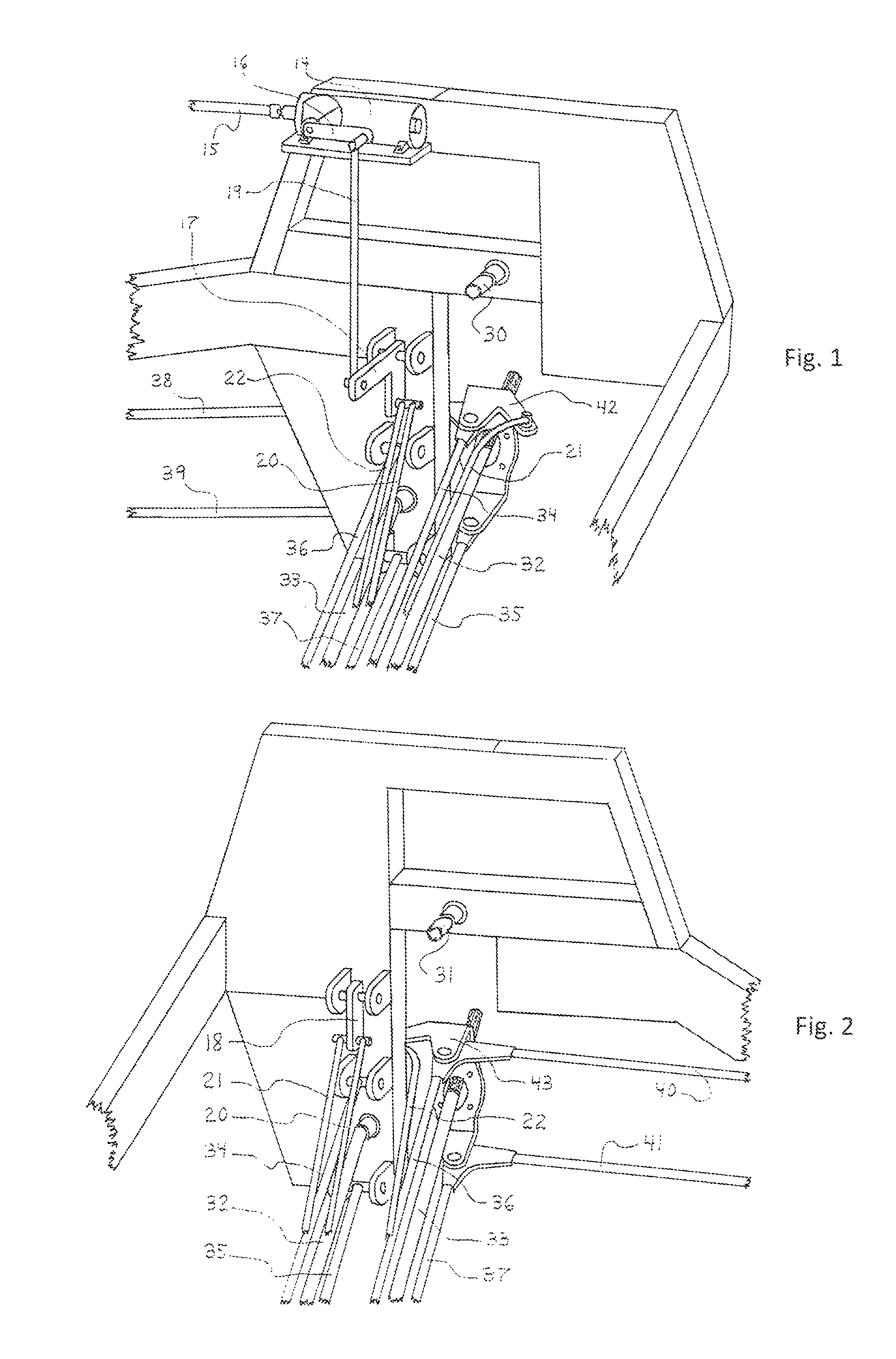
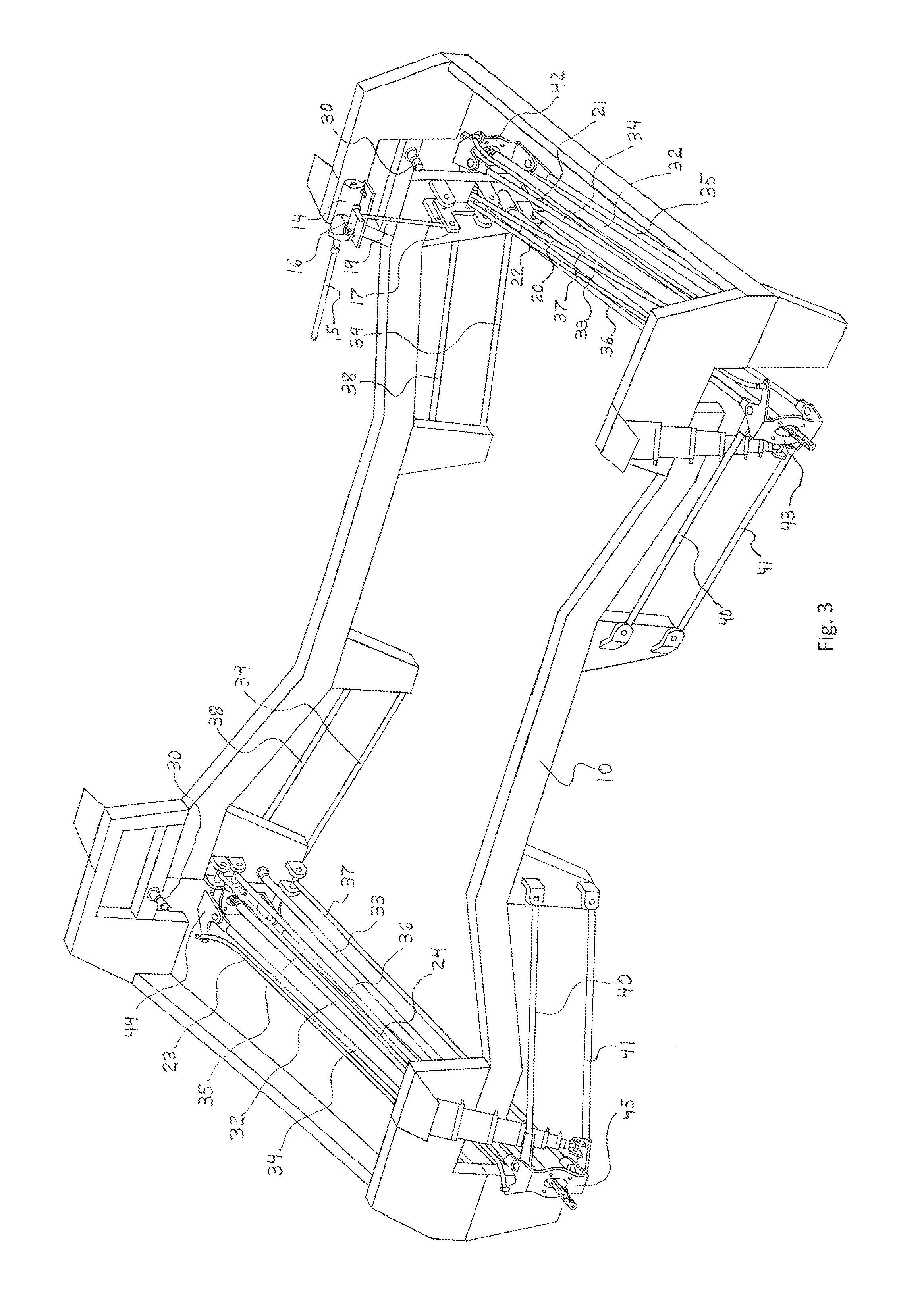
The present invention is a new steering system design for vehicles that uses a unique swingset lever arm linkage arrangement commonly found in off-road racing trucks. The system includes a Saginaw recirculating ball-type steering box, bellcrank, swingset arm, draglink, connector link, and tie rods. The steering system is designed to work with a powered version of the independent suspension system disclosed in U.S. patent application Ser. No. 14 / 087,552. The system uses a right-angle bellcrank and one tie rod per wheel, with the tie rod positioned to control the directional orientation of both steering and non-steering knuckles. The system also includes a swingset lever arm that transmits steering input to the front driver and passenger steering knuckles with minimal bump steer throughout suspension travel. The rear driver or passenger tie rod controls the straight-ahead orientation of the non-steering knuckle with minimal change in toe throughout suspension travel. The system uses a rigid attachment to lock the non-steering knuckle into a straight-ahead orientation. Overall, the steering system provides improved steering performance and control for vehicles.

Problems solved by technology

While the powered version introduces a unique means of transmitting power from a powertrain to the wheels, the suspension system lacks a means of controlling the directional orientation of the knuckles, the knuckles being rotatably attached to the wheels.

Method used


Image

  • Steering for independent suspension system
  • Steering for independent suspension system
  • Steering for independent suspension system

Examples


Embodiment Construction

[0058]The present invention represents a steering system designed to function with the powered version of the independent suspension system disclosed in U.S. patent application Ser. No. 14 / 087,552. The suspension system is based on Ford's twin I-beam front suspension system that incorporates a type of double A-arm configuration per wheel. The drivetrain includes a unique gearbox known as a reverse power coupler. Incorporated into the frame side, the reverse power coupler comprises external components including the input and output shafts and mounting brackets for the leading links in the suspension system.

[0059]Regarding the drawings, a steering system for a four-wheel drive vehicle is illustrated in detail and installed within a frame 10 in conjunction with a suspension system and drivetrain. Components of the steering system include a steering box 14, bellcrank 17, swingset arm 18 steering shaft 15, draglink 19, connector link 20, and front and rear driver and passenger tie rods 2...


PUM


Abstract

Disclosed herein is a novel steering system specifically designed to operate in conjunction with the powered version of the extreme-travel independent suspension system that is disclosed in the U.S. patent application Ser. No. 14 / 087,552. Based on a steering mechanism commonly found in off-road racing trucks built around Ford's twin I-beam front suspension system, this novel steering system comprises a type of swingset steering linkage structure. Unique features of this novel steering system include a right-angle bellcrank and swingset arm whereby the vertical bellcrank arm functions like the swingset arm. This novel steering system utilizes front or rear driver and passenger tie rods operating in coincidence with their counterpart suspension links to control the directional orientation of the steering or non-steering knuckles with minimal bump steer or change in toe throughout suspension travel, respectively.

Description

CROSS-REFERENCE TO RELATED APPLICATIONS[0001]This application represents a novel steering system specifically designed to operate in conjunction with the powered version of the extreme-travel independent suspension system. The powered version of this suspension system is covered in U.S. patent application Ser. No. 14 / 087,552.STATEMENT REGARDING FEDERALLY SPONSORED RESEARCH OR DEVELOPMENT[0002]Not ApplicableREFERENCE TO SEQUENCE LISTING, A TABLE, OR A COMPUTER PROGRAM LISTING COMPACT DISC APPENDIX[0003]Not ApplicableBACKGROUND OF THE INVENTION[0004]Disclosed in patent application Ser. No. 14 / 087,552 is a powered version of a novel independent suspension system. The novel suspension system is a type of double A-arm suspension system derived from Ford's twin I-beam front suspension system, this novel suspension system being covered in patent application Ser. No. 14 / 059,062. While the powered version introduces a unique means of transmitting power from a powertrain to the wheels, the su...

Claims


Application Information

Patent Timeline
Patent Type & Authority Patents(United States)
IPC IPC(8): B62D7/16B60G7/02B60G9/02
CPCB60G7/02B62D7/16B60G9/027B60G3/20B60G2200/1442B60G2300/07
Inventor BANDY, RONALD SCOTT
Owner BANDY RONALD SCOTT
Learn More