Supercharge Your Innovation With Domain-Expert AI Agents!

Assembly and method to attach a device such as a hydrofoil to an antiventilation plate

a technology of anti-ventilation plate and hydrofoil, which is applied in the field of marine operations, can solve the problems that boat owners are often reluctant to make such permanent modifications or to expend the time and effort necessary to make the modifications

Active Publication Date: 2015-09-01
SPORT MARINE TECH
View PDF81 Cites 2 Cited by
  • Summary
  • Abstract
  • Description
  • Claims
  • Application Information

AI Technical Summary

Benefits of technology

The present invention is an assembly for mounting a hydrofoil to a marine component, such as a plate. The assembly includes a first device with mounting disk assemblies on both sides of the plate. The mounting disk assembly has a step and a friction surface for attachment to the plate, as well as a bolt to secure the assembly to the plate. Additionally, a catch is used to further mount the assembly to the plate. The use of multiple mounting disk assemblies and a catch ensures stability and secure mounting of the hydrofoil to the plate.

Problems solved by technology

Unfortunately, the mounting of such a hydrofoil often requires a permanent modification of the outboard motor or sterndrive, such as drilling holes to receive bolts, for example.
Boat owners are often reluctant to make such permanent modifications or to expend the time and effort necessary to make the modifications.

Method used


Image

  • Assembly and method to attach a device such as a hydrofoil to an antiventilation plate
  • Assembly and method to attach a device such as a hydrofoil to an antiventilation plate
  • Assembly and method to attach a device such as a hydrofoil to an antiventilation plate

Examples


first embodiment

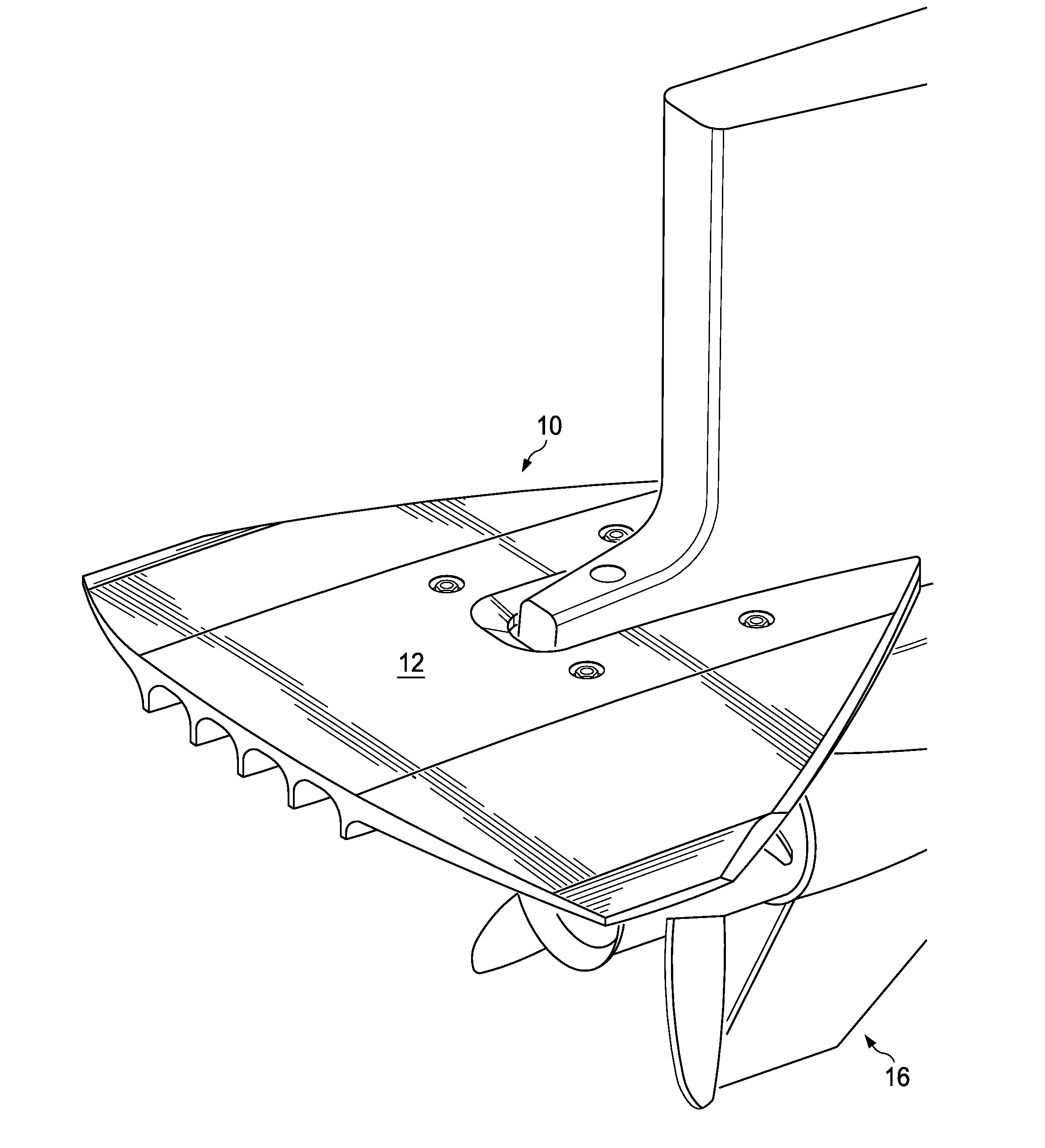
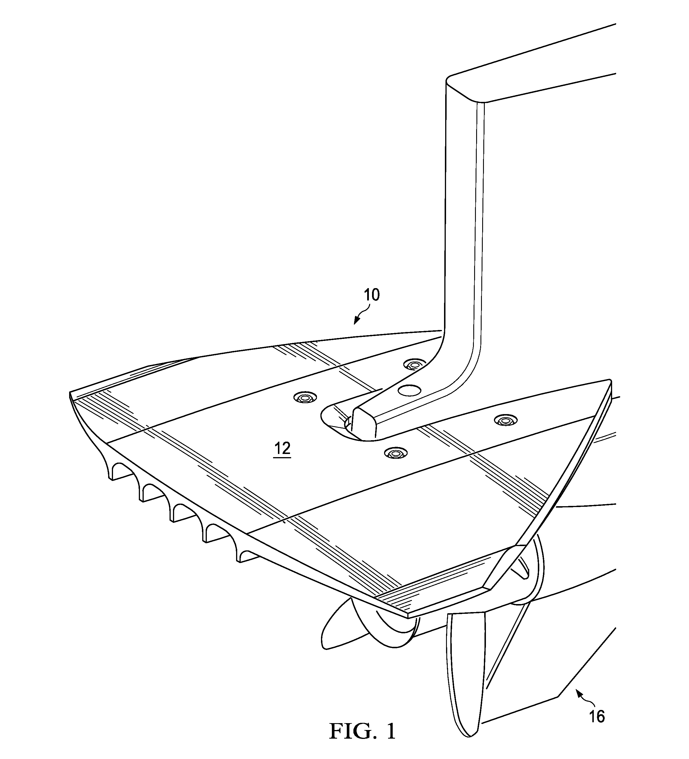
[0043]With reference now to the figures, FIGS. 1-13 and, 16-18 illustrate an assembly 10 forming the present invention. The assembly 10 is shown to mount a hydrofoil 12 on the anti-ventilation plate 14 (also commonly called a cavitation plate) of an outboard motor 16 without any need to modify, drill or otherwise permanently change the plate 14 or outboard motor 16. While an outboard motor 16 is shown, the assembly 10 could be used with a sterndrive (inboard / outboard). Further, while assembly 10 is shown to mount a hydrofoil, it could also mount a trolling motor or a trolling plate extending behind the propeller used to reduce thrust, or other accessory.

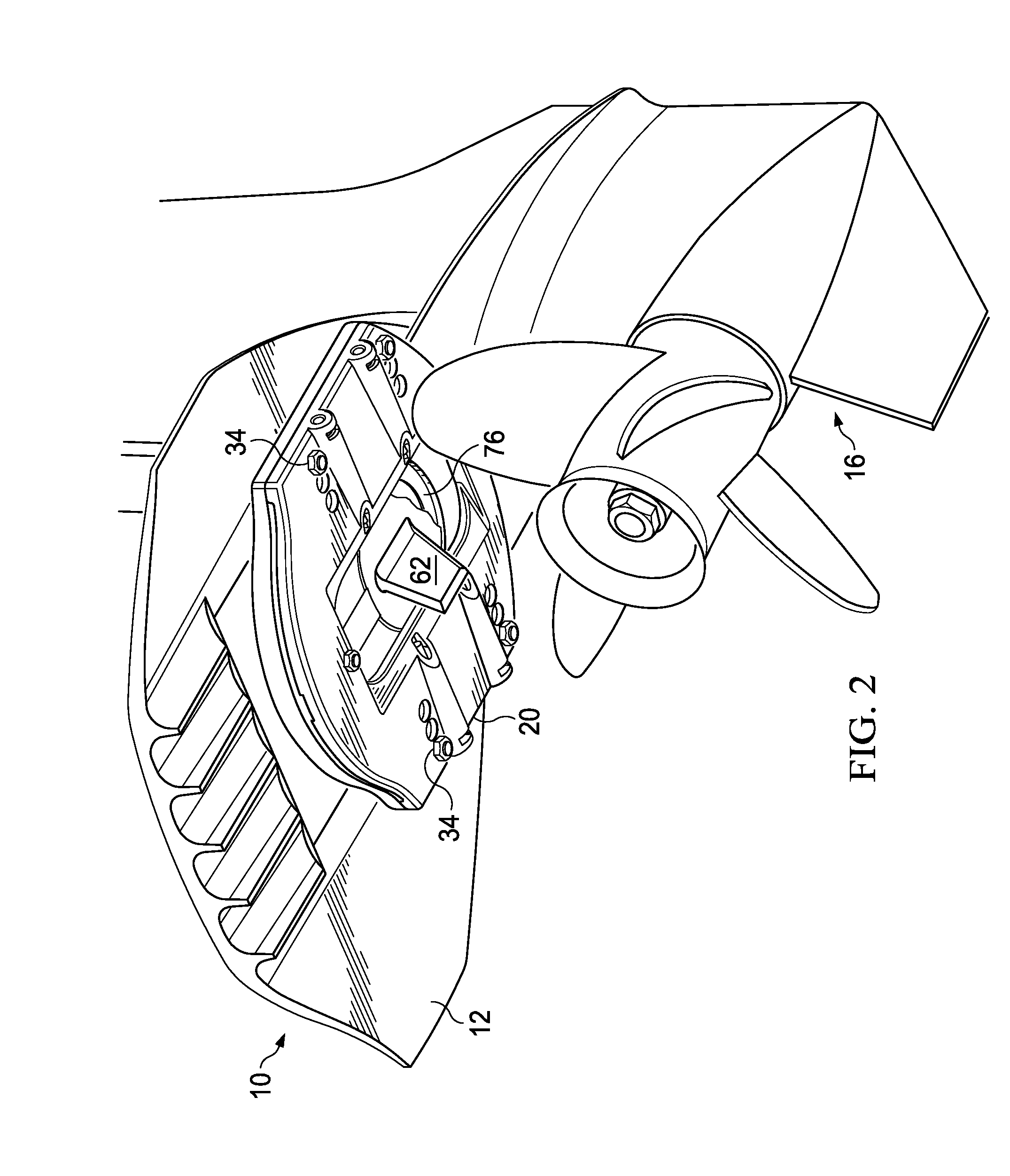
[0044]With reference to FIGS. 3 and 4, the assembly 10 can be seen to include a lower element 20 and an upper element 22. The lower and upper elements 20 and 22 are preferably made of plastic, but could be made of metal, such as aluminum, or other suitable material. Each side 24 and 26 of element 20 and each side 28 and 30 of element...

second embodiment

[0056]With reference now to FIGS. 14 and 15, the present invention is illustrated forming assembly 100. Assembly 100 uses the identical lower element 20, but has an upper element 122 which actually is formed as a hydrofoil 124. Preferably, the upper element 122 also has a series of inline holes 134 to allow the assembly to be secured to different width plates 14. In all aspects of attachment, the upper and lower elements 122 and 20 of assembly 100 operate the same as upper and lower elements 22 and 20 of assembly 10.

third embodiment

[0057]With reference now to FIGS. 23-29, there is illustrated an assembly 200, including a hydrofoil 202, forming the present invention. The assembly 200 is mounted on the anti-ventilation plate 14 (also commonly called a cavitation plate) of the outboard motor 16 without any need to modify, drill or otherwise permanently change the plate 14 or outboard motor 16. While an outboard motor 16 is shown, the assembly 200 could be used with a sterndrive (inboard / outboard). Further, while assembly 200 is shown to include a hydrofoil, it could also form a trolling motor or a trolling plate extending behind the propeller used to reduce thrust, or other accessory.

[0058]The assembly 200 includes a hydrofoil 202 and a series of four mounting disk assemblies 204 which clamp the hydrofoil 202 to the anti-ventilation plate 14. A catch 206 is also secured between the trim tab recess 76 of the plate 14 and the hydrofoil 202.

[0059]The hydrofoil 202 can be seen to have dual series of three inline hole...


PUM


Abstract

An assembly (300), including a hydrofoil (302), is provided for mounting on the anti-ventilation plate (14) of a sterndrive or outboard motor (16) without the need to modify the plate or motor. The hydrofoil (302) of the assembly (300) has a series of holes (308) spaced along its width to receive a series of mounting disk assemblies (304) having a stepped disk (310). A carriage bolt (314) forming a part of each mounting disk assembly (304) is placed in the hole (308) closest the edge (36, 38) of the plate (14), a stepped disk (310) is placed over the end of the bolt (314) and the hydrofoil (302) is clamped on the plate (14) by tightening nuts (316) to clamp the plate (14) between the hydrofoil (302) and step (362) of the disk (310). Friction material (312) on the mounting disk assemblies provides firm engagement with the plate (14). A catch (206) can be mounted between the hydrofoil (302) and the trim tab or anode recess (76) in the plate (14).

Description

CROSS REFERENCE TO RELATED APPLICATION[0001]This application is a continuation in part of pending U.S. patent application Ser. No. 13 / 658,907 filed Oct. 24, 2012, which is a continuation in part of pending U.S. patent application Ser. No. 13 / 066,288 filed Apr. 11, 2011, which is a continuation in part of U.S. patent application Ser. No. 12 / 150,598 filed Apr. 29, 2008, now U.S. Pat. No. 8,043,135 issued Oct. 25, 2011.TECHNICAL FIELD[0002]This invention relates to marine operations, and in particular to a boating accessory.BACKGROUND OF THE INVENTION[0003]Many boaters find it desirable to mount a hydrofoil on the outboard motor or sterndrive of a pleasure boat. The hydrofoil is believed to provide enhanced efficiency and speed in boat operation. Examples of such hydrofoils are illustrated in US Design Patents D352,023 issued Nov. 1, 1994 and D363,914 issued Nov. 7, 1995, the disclosures of which is hereby incorporated by reference.[0004]Unfortunately, the mounting of such a hydrofoil ...

Claims


Application Information

Patent Timeline
IPC IPC(8): B63H1/18B63H1/28B63H5/16B63B17/00B63B1/24
CPCB63B1/242B63B17/00B63H20/34
Inventor CORN, JAMES F.
Owner SPORT MARINE TECH
Features
  • R&D
  • Intellectual Property
  • Life Sciences
  • Materials
  • Tech Scout
  • Unparalleled Data Quality
  • Higher Quality Content
  • 60% Fewer Hallucinations
Learn More