
Grommet assembly

a technology for grommets and assembly parts, applied in the direction of insulating bodies, cable arrangements between relatively moving parts, manufacturing tools, etc., can solve the problems of increasing management costs and overall product costs, poor assembly workability, and large number of assembly man-hours, so as to improve assembly workability, improve the water resistance of an automobile door, and ensure the water resistance of a part.

Active Publication Date: 2008-09-02
YAZAKI CORP
View PDF14 Cites 27 Cited by
  • Summary
  • Abstract
  • Description
  • Claims
  • Application Information

AI Technical Summary

Benefits of technology

[0013]In view of the above problems, an object of the invention is to provide a grommet assembly and its assembly structure that allow assembly work with good workability and a reduced number of components and that show reliable water resistance.

Problems solved by technology

This presents a problem of poor assembly workability that requires a large number of man-hours of assembly and a problem of an increased management cost and overall product cost due to an increased number of components such as the bolt 99, the inner member 83 and the protector 84 for protecting electric wires.

Method used


Image

  • Grommet assembly
  • Grommet assembly
  • Grommet assembly

Examples


first embodiment

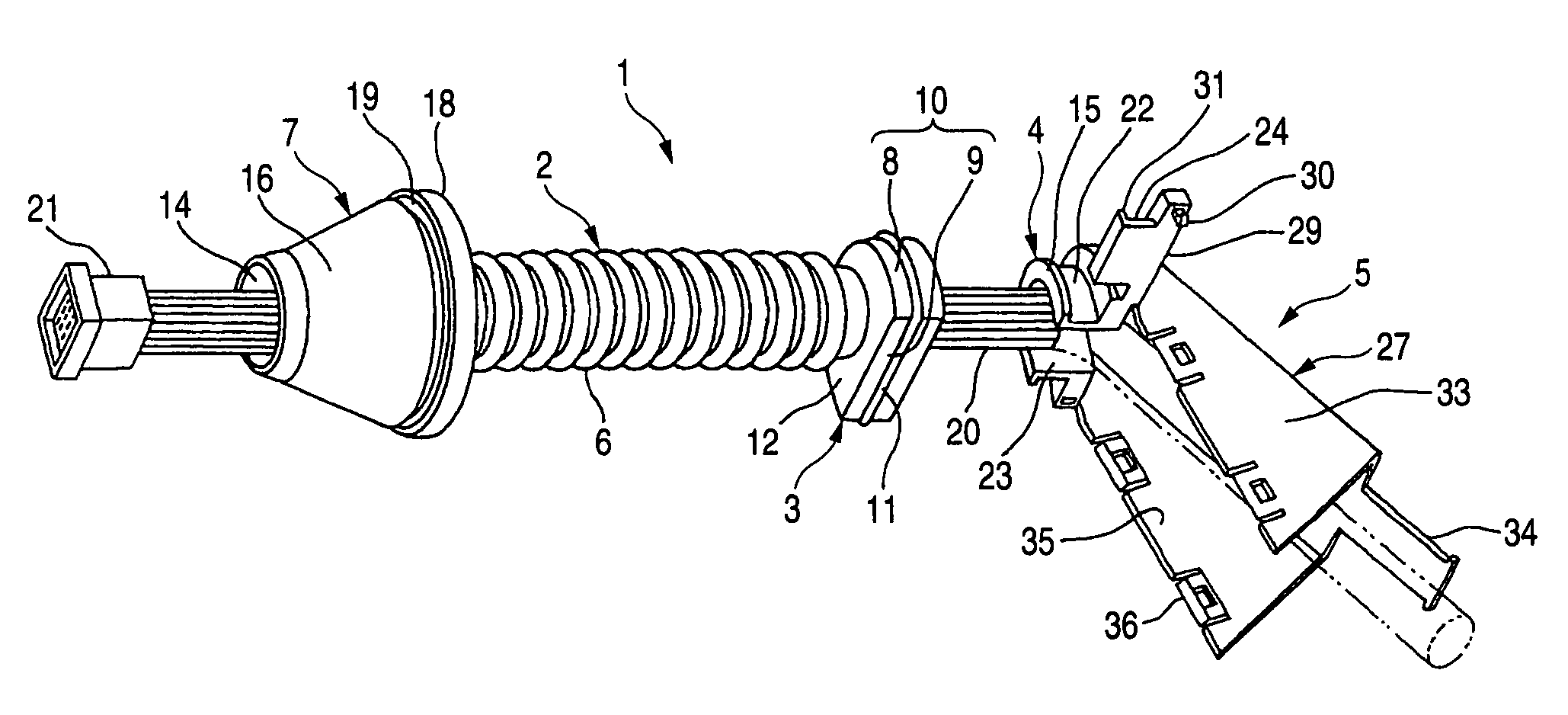
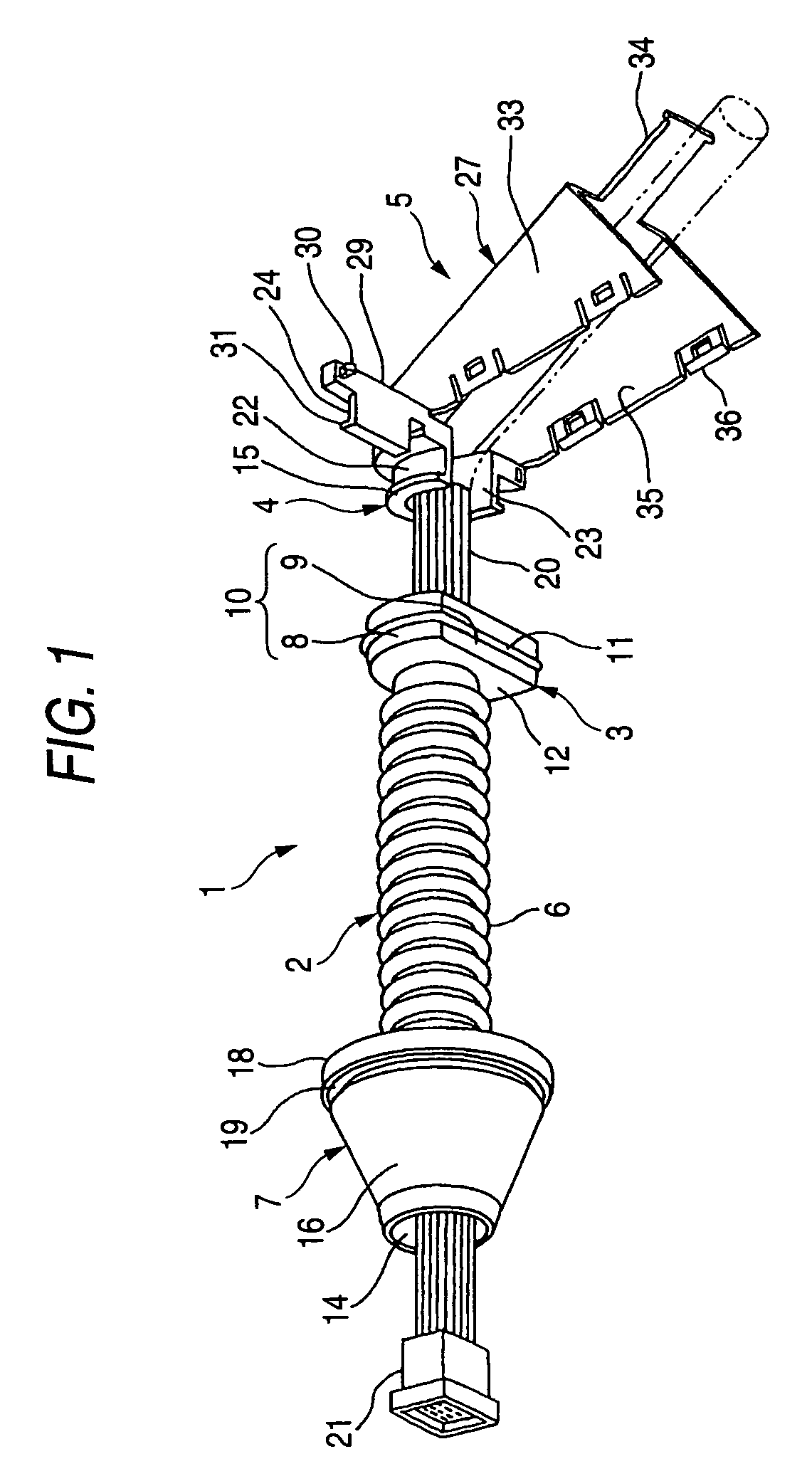
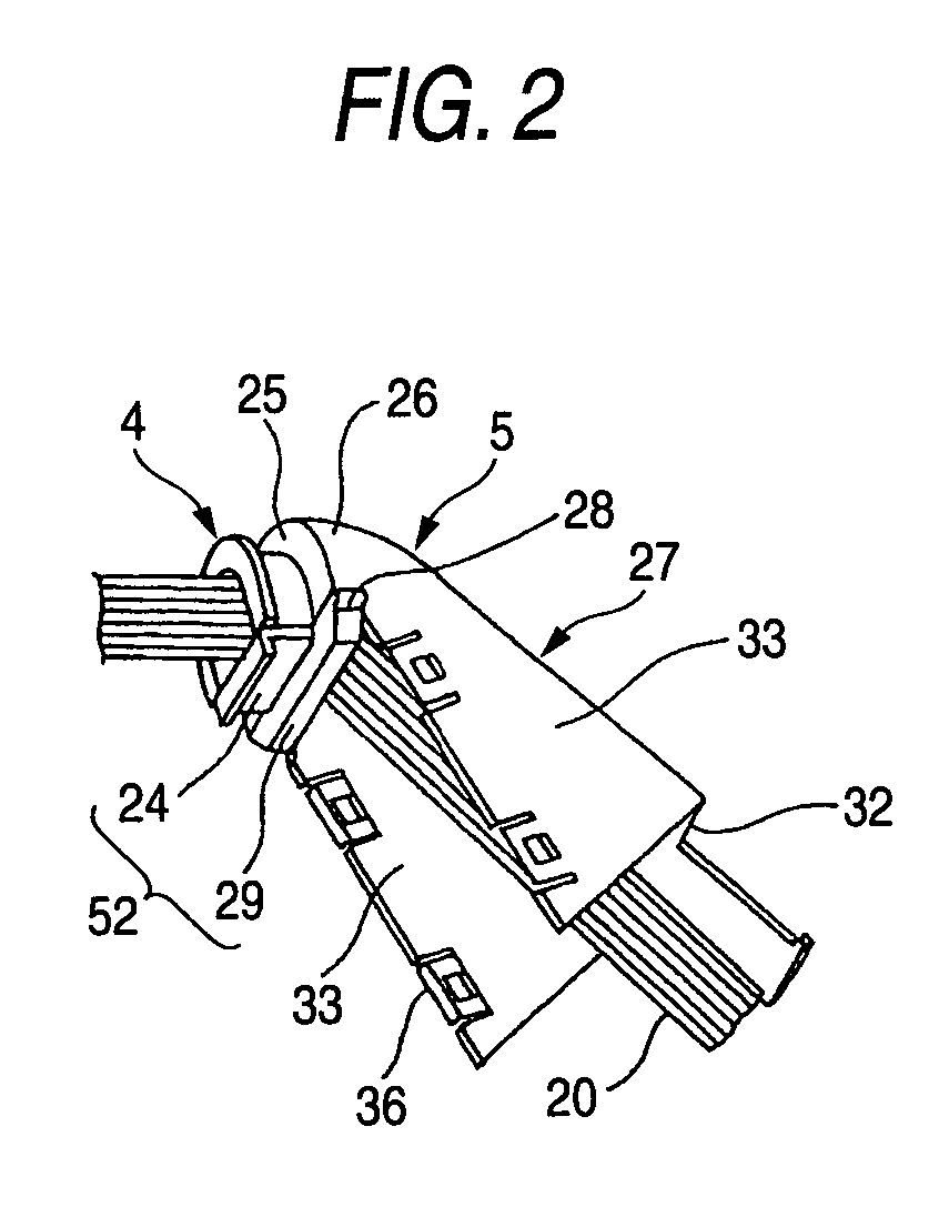
[0060]FIGS. 1 through 6 show a door grommet assembly according to the invention.

[0061]As shown in FIG. 1, the door grommet assembly 1 comprises an elastic grommet main body 2 made of a synthetic rubber and an integral inner-cover 5 made of a synthetic resin integrated with a hard opening-closing inner member 4 that is fitted into the collar part 3 of the grommet main body 2.

[0062]The grommet main body 2 comprises a telescopic bellows part 6, a collar part 3 formed integrally with the base end of the bellows part 6, and a cup-shaped part 7 formed integrally with the tip of the bellows part 6. The collar part 3 is formed slightly longer than a semicircle as seen from the front and comprises an outer peripheral wall 10 including curved outer peripheral surfaces 8 and a straight outer surface (plane) 9, a lip part 11 for reinforcing water resistance annularly formed at the center of the outer peripheral wall 10 in its peripheral direction (perimeter) integrally therewith, a wall 12 on t...

second embodiment

[0087]While the curved wall 43 is arranged on the door panel 39 and the flat wall 44 is arranged on the door trim 37 in the above embodiment, it is possible to arrange the curved wall (43) on the door trim 37 and arrange the flat wall (44) on the door panel 39. This is also the case with the second embodiment described later.

[0088]FIGS. 7 through 16 show the second embodiment of a door grommet assembly and its assembly structure according to the invention.

[0089]As shown in FIG. 7, the door grommet assembly 53 is composed of an elastic grommet main body 1 made of a synthetic rubber and a hard inner member 54 made of a synthetic resin fitted to the inside of the collar part 3 of the grommet main body 2. The inner member 54 is pushed by the pressing member 55 on a door trim 37′ so as to bring the collar part of the grommet main body 2 into close contact with the front wall 44 of the door trim 37′.

[0090]The shape of the grommet main body 2 is similar to that in the first embodiment. The...


PUM


Abstract

Provided is a grommet assembly including an elastic grommet main body and hard inner members to be fitted into the collar part of the grommet main body where openings for inserting electric wires are notched in part of the peripheral wall of the inner member. A lid wall is closed on an opening by way of a locking unit. A cover for protecting electric wires is integrally arranged on the inner member. The outer peripheral surface of the collar part is clamped between a door panel and a door trim. The cover is locked to the door trim by way of the locking unit. An elastic pressing member is arranged on the door trim in order to engage the pressing member with the inside of the collar part of the grommet main body thus clamping the collar part between itself and the door trim.

Description

BACKGROUND OF THE INVENTION[0001]1. Field of the Invention[0002]The present invention relates to a door grommet assembly to be assembled, with excellent water resistance, to a door of an automobile with a plurality of electric wires inserted and its assembly structure.[0003]2. Related Art[0004]FIG. 15 shows the form of a related art door grommet assembly (refer to JP-A-2001-354085).[0005]The door grommet assembly 81 is composed of a grommet main body 82 made of a synthetic rubber, a hard inner member 83 made of a synthetic resin insert-molded into the grommet main body 82, and a protector 84 locked as opposed to the inner member 83.[0006]The grommet main body 82 is composed of a collar part 85, a bellows part 86 protruding from the collar part, and a cup-shaped part 87 integrated with the front end of the bellows part 86. On the inner surface of the collar part 85 is integrally formed the inner member 83. In the inner member 83 is provided a hole 88 in communication with the bellows...

Claims


Application Information

Patent Timeline
Patent Type & Authority Patents(United States)
IPC IPC(8): H02G3/22H02G3/18
CPCB60R16/0222H02G11/00Y10T16/05Y10T16/063
Inventor TSUKAMOTO, MASASHIIKEDA, KOJI
Owner YAZAKI CORP
Learn More