Cell frame for redox flow battery, and redox flow battery

a cell frame and redox flow technology, applied in the direction of secondary cell details, non-aqueous electrolyte cells, indirect fuel cells, etc., can solve the problems of inability to effectively prevent electrolyte leakage between the cell frame and the cell frame, and poor workability in cell stack assembly, etc., to suppress losses, reduce pressure losses in the electrolyte circulation, and reduce losses. the effect of electric current flowing in the electroly

a cell frame and redox flow technology, applied in the direction of secondary cell details, non-aqueous electrolyte cells, indirect fuel cells, etc., can solve the problems of inability to effectively prevent electrolyte leakage between the cell frame and the cell frame, and poor workability in cell stack assembly, etc., to suppress losses, reduce pressure losses in the electrolyte circulation, and reduce losses. the effect of electric current flowing in the electroly

US20080081247A1Inactive Publication Date: 2008-04-03SUMITOMO ELECTRIC IND LTD +1

Image

  • Cell frame for redox flow battery, and redox flow battery
  • Cell frame for redox flow battery, and redox flow battery
  • Cell frame for redox flow battery, and redox flow battery

Examples


example 1

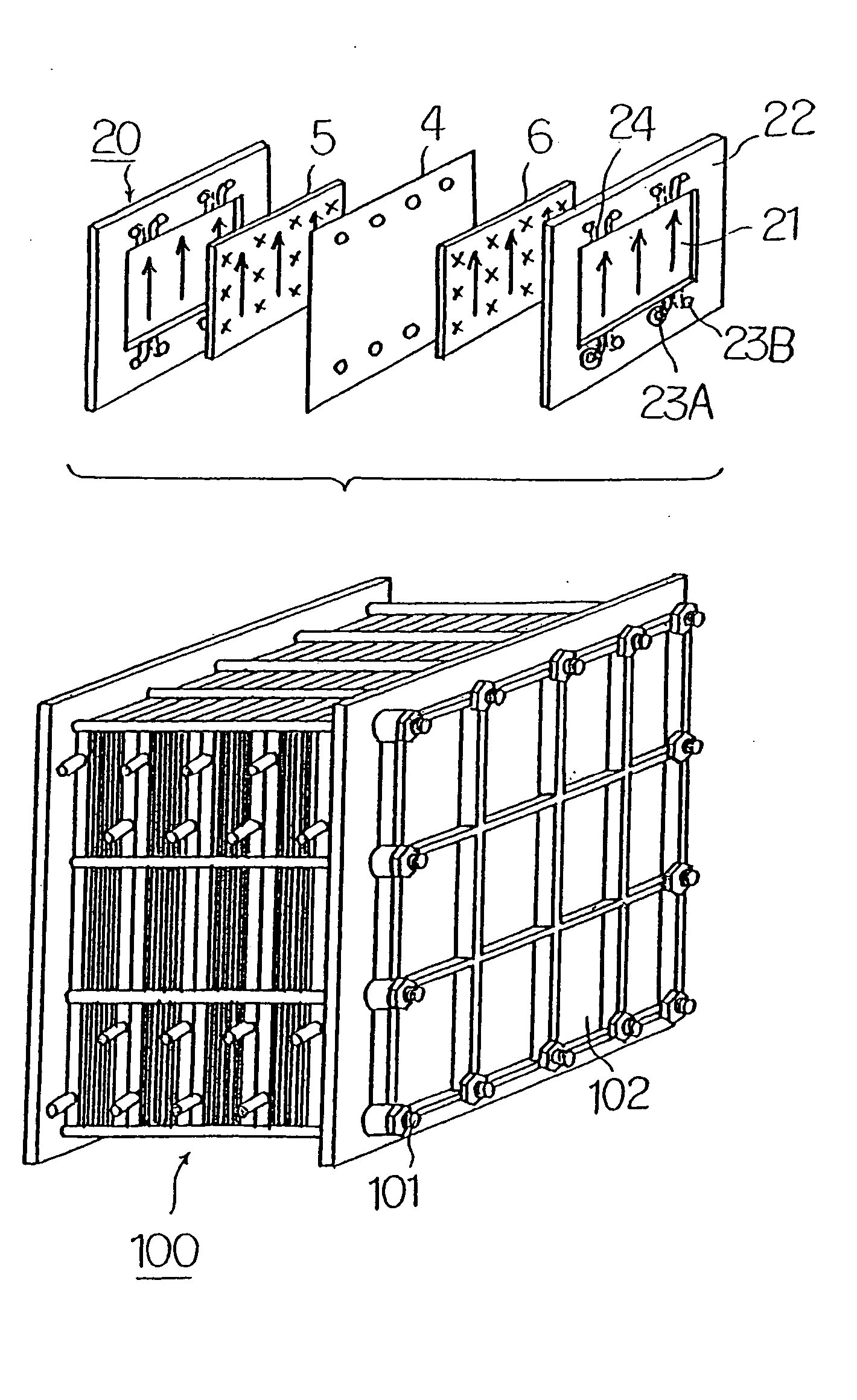
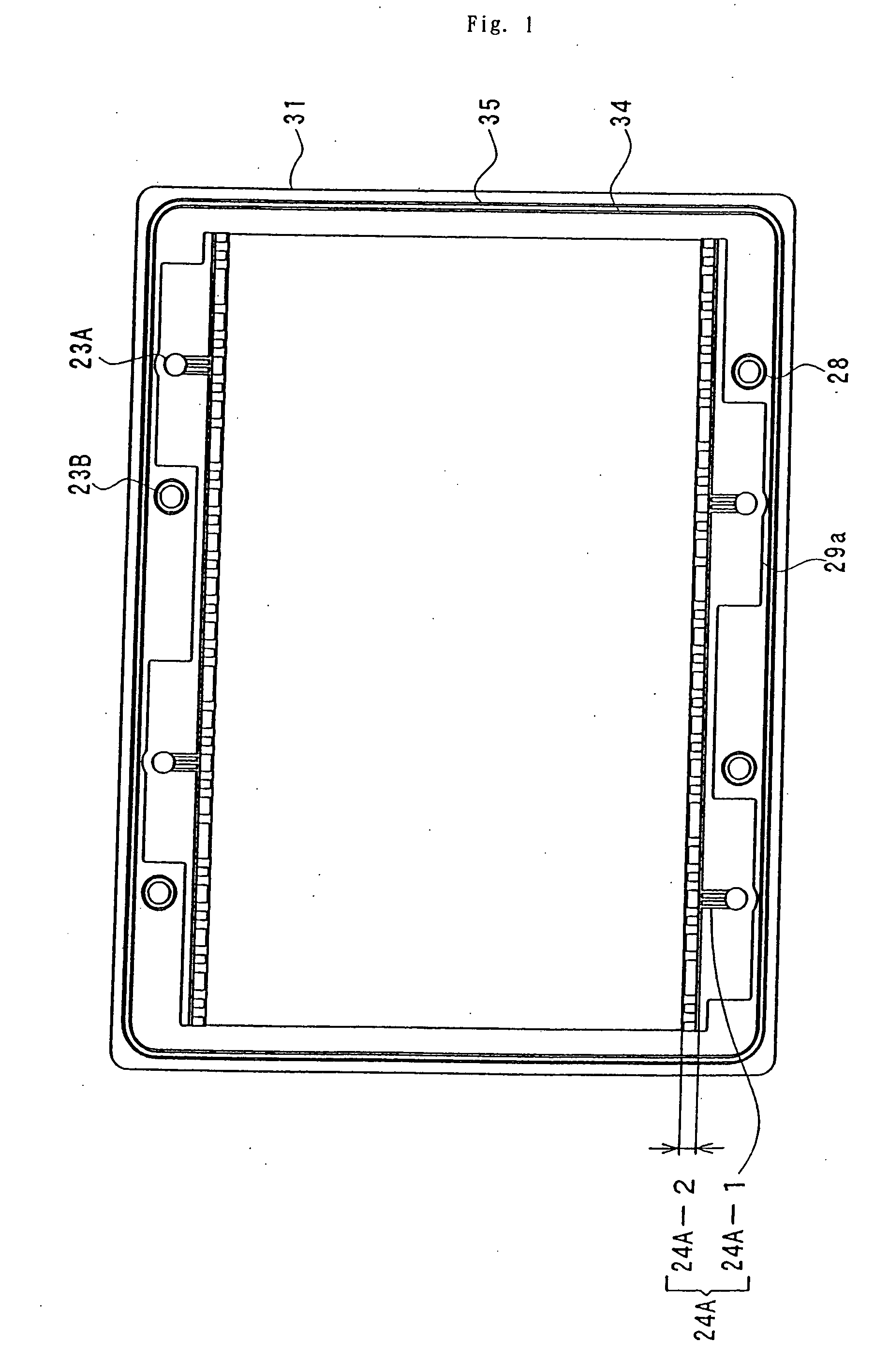
[0069] Using the cell stack mentioned above, a redox flow secondary battery was produced, and battery performances and discharge possible power of that redox flow secondary battery were measured. Data on material, size, and others of the cell stack and measurement results are shown below.

[0070] Size

[0071] Outer size: 1,000 mm wide, 800 mm high, and 5 mm thick,

[0072] Inner size: 900 mm wide and 600 mm high,

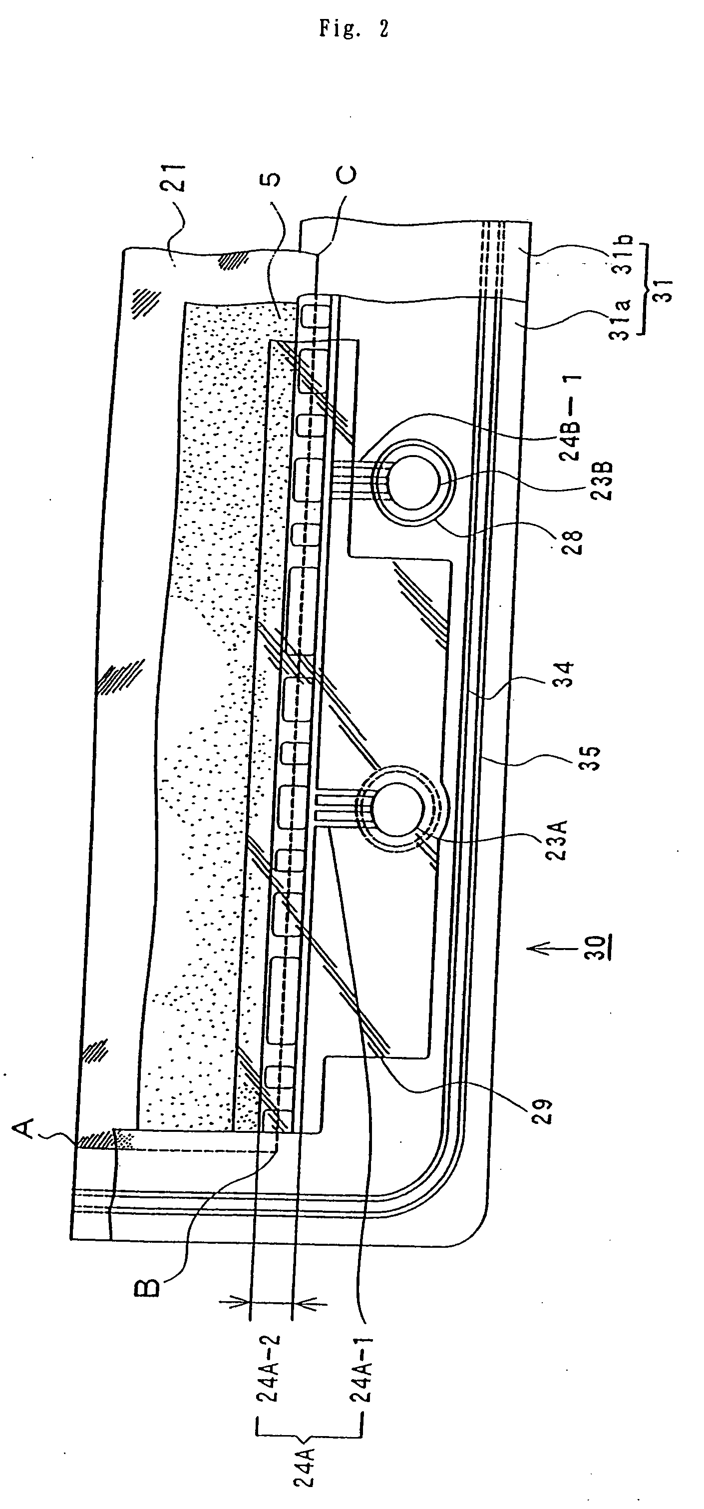
[0073] Seal groove: 3 mm wide, 1 mm deep, and 5 mm in distance between grooves,

[0074] O-ring size: 1.5 mm in diameter of cross-section of the ring, and 1,000 mm in diameter,

[0075] Inner and outer seal grooves: Arranged at the same locations on both sides of the cell frame,

[0076] Ratio of diameter of manifold to total width of cell frame: 3%,

[0077] Ratio of distance between adjacent manifolds to total width of cell frame: 30%,

[0078] Cross-sectional area of guide groove: 5 mm2,

[0079] Material: Resin comprising 50 mass % vinyl chloride and 50 mass % acrylonitrile-butadiene-s...

example 2

[0094] Using the cells of the present invention, a different redox flow secondary battery from that of Example 1 was produced, and battery performances and discharge possible power of that redox flow secondary battery was measured. Differences in data on material, size, and others of the cell stack from those of Example 1 and measurement results are shown below.

[0095] Size

[0096] Outer size: 1,000 mm wide, 500 mm high, and 4 mm thick,

[0097] Inner size: 900 mm wide and 300 mm high,

[0098] Seal groove: 2 mm wide, 1 mm deep, and 5 mm in distance between grooves,

[0099] O-ring size: 1.5 mm in diameter of cross-section of the ring, and 750 mm in diameter,

[0100] Inner and outer seal grooves: Arranged on both sides of the cell frame at the locations shifted 8 mm away from each other,

[0101] Ratio of diameter of manifold to total width of cell frame: 2%,

[0102] Ratio of distance between adjacent manifolds to total width of cell frame: 35%,

[0103] Material: Resin comprising 90 mass % viny...


PUM

PropertyMeasurementUnit
distanceaaaaaaaaaa
areaaaaaaaaaaa
thicknessaaaaaaaaaa

Abstract

This invention provides a cell frame for a redox flow battery that prevents leakage of electrolyte out of the cell frame and also provides a good workability in assembling the redox flow battery. Also, this invention provides a redox flow battery using the cell frame. In the cell frame 30 for the redox flow battery 30 comprising a bipolar plate 21 and a frame 31 fitted around a periphery of the bipolar plate 21, the frame 31 has, on each side thereof, an inner seal and an outer seal to press-contact with a membrane and also seal electrolyte. The frame 31 has, on each side thereof, an inner seal groove 34 and an outer seal groove 35 for placing therein the inner seal and the outer seal, respectively, to prevent the electrolyte from leaking out, and O-rings are placed in the respective seal grooves.

Description

TECHNICAL FIELD [0001] The present invention relates to a cell frame for a redox flow battery designed to effectively prevent leakage of electrolyte out of the cell frame and to a redox flow battery using the same. BACKGROUND ART [0002] Referring to FIG. 8, there is shown an explanatory view showing an operating principle of a conventional redox flow secondary battery. The redox flow battery has a cell 1 separated into a positive electrode cell 1A and a negative electrode cell 1B by a membrane 4 that can allow ions to pass through. The positive electrode cell 1A and the negative electrode cell 1B include a positive electrode 5 and a negative electrode 6, respectively. A positive electrode tank 2 for feeding and discharging positive electrolytic solution to and from the positive electrode cell 1A is connected to the positive electrode cell 1A through conduit pipes 7, 8. Similarly, a negative electrode tank 3 for feeding and discharging negative electrolytic solution to and from the n...

Claims


Application Information

Patent Timeline
03 Apr 2008
Publication
US20080081247A1
IPC
H01M2/02; H01M2/38; F16J15/10; H01M2/08; H01M8/02; H01M8/18; H01M8/20; H01M8/24; H01M10/02
CPC
H01M8/0273; H01M8/0278; Y02E60/528; H01M8/188; H01M8/0291; H01M8/0289; Y02E60/50
Inventors
NAKAISHI, HIROYUKI; KANNO, TAKASHI