

Attaching structure
a technology of fixing structure and fixing hole, which is applied in the direction of washstands, lighting support devices, instruments, etc., can solve the problems of increased insertion force into the fixing hole, poor workability, and bending force of the locking claw
- Summary
- Abstract
- Description
- Claims
- Application Information
AI Technical Summary
Benefits of technology
Problems solved by technology
Method used
Image

Examples
first embodiment
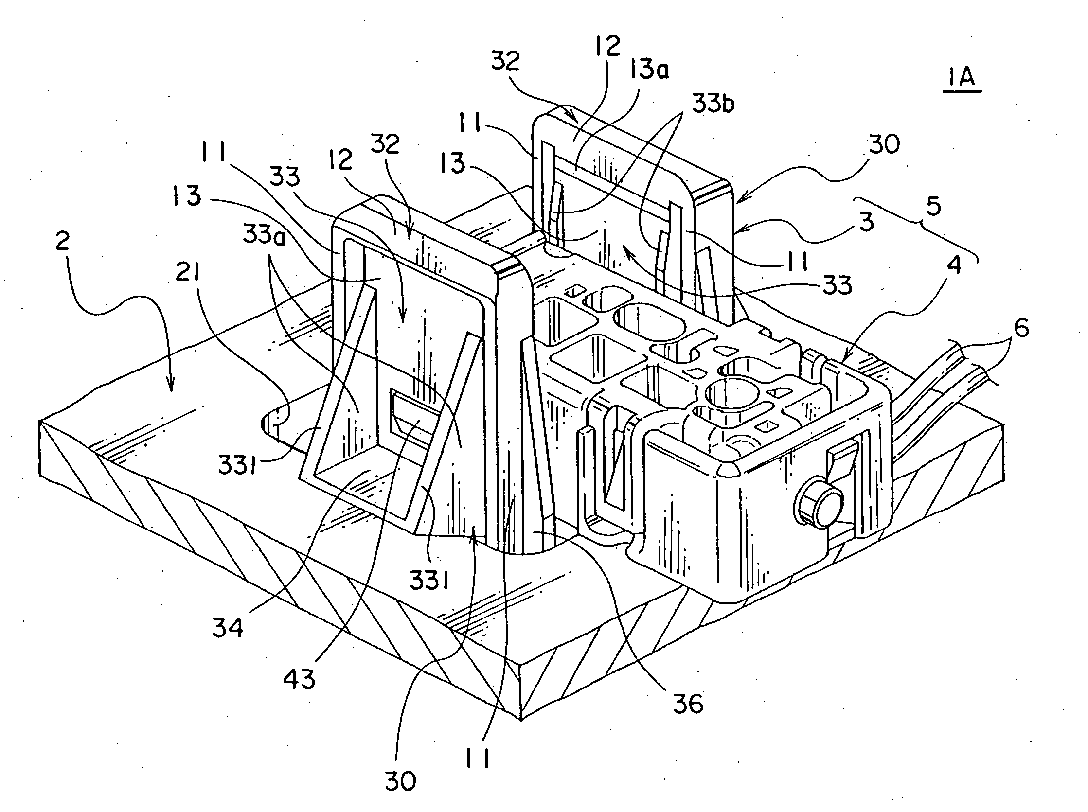
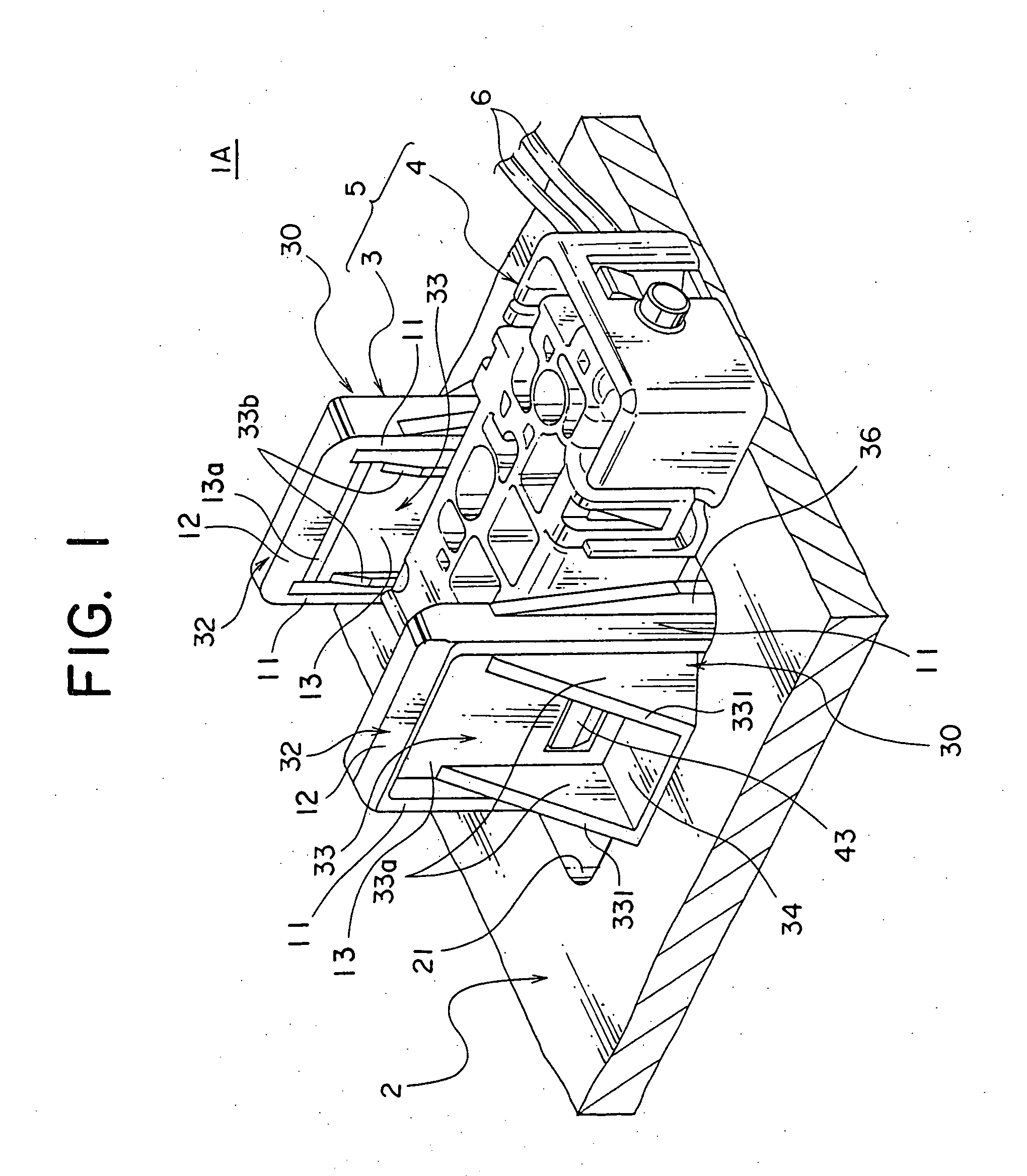
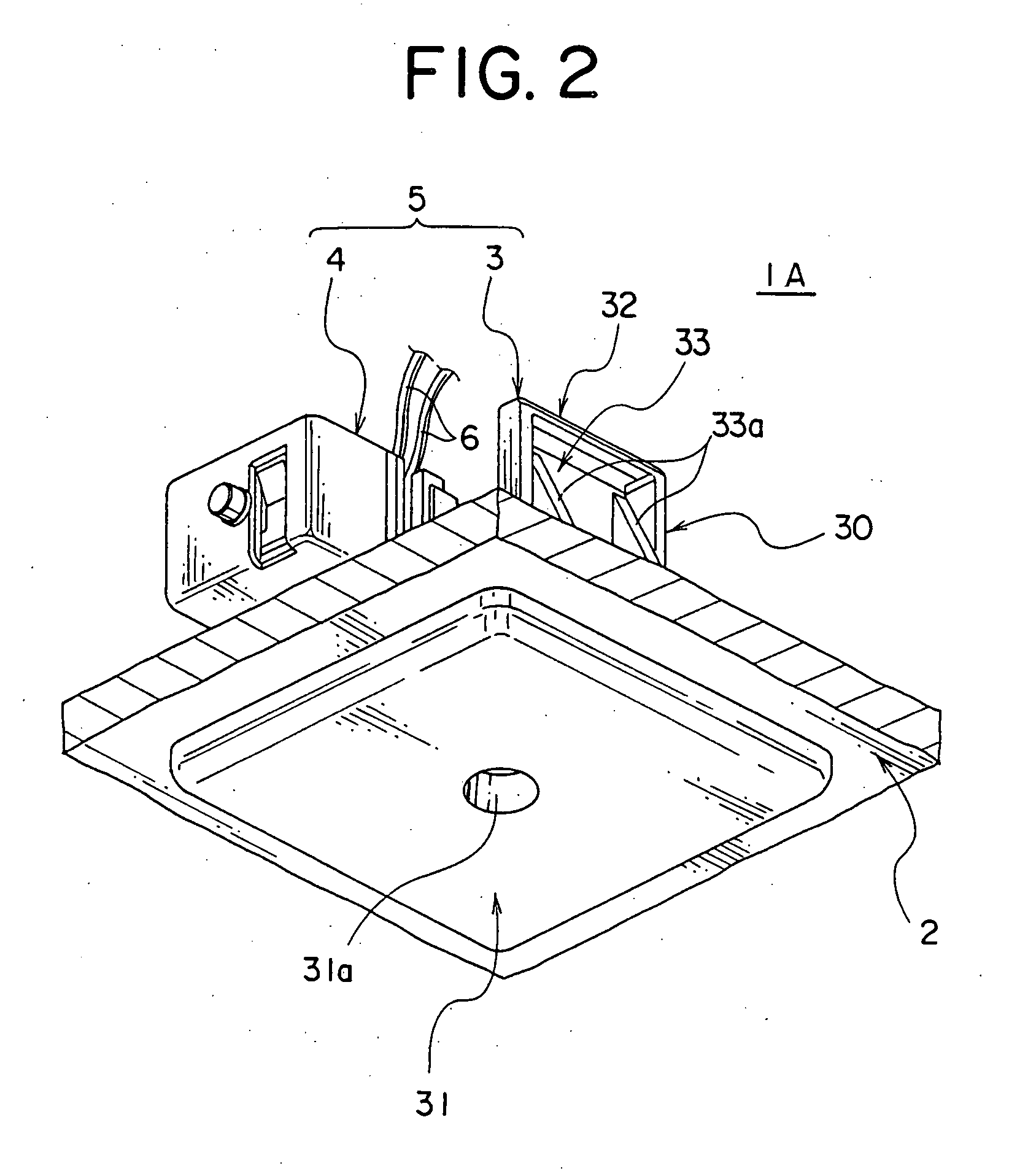
[0045]An attaching structure 1A according to the present invention will be explained with FIGS. 1 to 9. As shown in FIGS. 1 to 2, according to the attaching structure 1A, a room lighting system for a vehicle (hereunder referred to as lamp unit 5) as an attaching object is attached to an attaching hole 21 formed on a roof trim 2 of a vehicle as a panel. The roof trim 2 is made of synthetic resin and composes a roof of a vehicle. The roof trim 2 is mounted on an inside of a cabin. The lamp unit 5 illuminates the inside of the cabin, and as shown in FIG. 1, includes a design part 3 as a first part and a function part 4 as a second part.
[0046]As shown in FIG. 3, the function part 4 includes a light source such as an LED (light emitting diode) or a light bulb in a housing 40 formed in a substantially rectangular shape and made of synthetic resin. A translucent window 42 is mounted on a bottom wall 41a of the housing 40 for guiding the light from the light source to the cabin. The translu...
second embodiment
[0080]Next, an attaching structure 1B according to the present invention will be explained with reference to FIGS. 11 to 14.
[0081]As shown in FIG. 11, in the attaching structure 1B, a room lighting system for a vehicle (hereunder referred to as lamp unit 5″) as the attaching object is attached to the attaching hole 21 formed on the roof trim 2 of the vehicle as the panel. The lamp unit 5″ is identical to those in the attaching structures 1A, 1A′ except a design part 103.
[0082]The design part 103 is made of resilient synthetic resin, and includes: the plate part 31 composing the outside appearance; and a pair of vertically extending parts 130 facing each other, and vertically extended from the plate part 31 to be positioned at the rear side of the attaching hole 21, namely, the ceiling side.
[0083]Each vertically extending part 130 includes: a connecting part 132 vertically extended from the plate part 31; a main part 133 continued to the connecting part 132 at a far side from the pla...
third embodiment
[0101]Next, an attaching structure 1C according to the present invention will be explained with reference to FIGS. 15 to 20.
[0102]As shown in FIG. 15, the attaching structure 1C is a structure for attaching a room lighting system (hereafter referred to as a lamp unit 5′″) as the attaching object to the attaching hole 21 formed on the roof trim 2 of a vehicle as the panel. The lamp unit 5′″ is the same as those in the attaching structure 1A, 1A′, 1B except the design part 303, namely, the function part 4.
[0103]The design part 303 is made of resilient synthetic resin. As shown in FIG. 16, the design part 303 includes: the plate part 31 composing the outside appearance of the lamp unit 5′″; a pair of vertically extending parts 330 facing each other, and vertically extended from the plate part 31 to be positioned at the rear side of the attaching hole 21, namely, the ceiling side; and the function part positioning part 35.
[0104]Each vertically extending part 330 includes: a main part 8 ...
PUM
 Abstract
Description
Claims
Application Information