Spin stabilized projectile trajectory control

a projectile trajectory and stabilized technology, applied in the field of ballistics, can solve the problems of complex epicyclic motion, inability to adapt the above-described methods to widespread use, and inability to achieve the effect of reducing the probability of a single projectile falling off,

Active Publication Date: 2011-06-21
SIMMONDS PRECISION PRODS
View PDF66 Cites 30 Cited by
  • Summary
  • Abstract
  • Description
  • Claims
  • Application Information

AI Technical Summary

Problems solved by technology

In free flight after muzzle exit, aerodynamic forces act on the projectile body, producing a complex epicyclic motion of nutation and precession throughout the trajectory that may affect, and otherwise interfere with, a desired trajectory of the projectile.
The previously proposed methods of trajectory correction are generally operationally limited or require complex implementation that may not be cost effective, such that none of the above-described methods have been adapted into widespread use.
For example, dragster devices must be fired to over-shoot the target, and can only correct for down-range errors, not cross-range errors.
Meteorological data that is not up-to-date (“stale MET”), or that is gathered at a location some distance from the projectile, may result in substantial cross-range errors that may not be corrected by one-dimensional dragster devices.
Canard devices may substantially increase drag of the projectile when deployed, thereby decreasing efficiency.
Canards and their actuating mechanisms may also occupy large volumes of restricted space within the projectile, and require substantial power resources to operate.
The relatively high drag of canard devices when deployed to control the projectile flight path may restrict the use of canard devices, in practice, to the terminal phase of the trajectory to avoid unacceptable range penalties.
However, deployment late in the trajectory may reduce the total correction capability (“maneuver authority”) of the canard devices.
Moreover, it may not be practical to arrange the canards to be retractable as well as deployable because of power, weight and complexity constraints.
Thruster devices may need to be small to fit within the restricted available space of the projectile, and the trajectory correction capability of the thruster devices may be strictly limited.
For thrusters positioned other than near the center of mass, thruster operation may induce excessive oscillations that affect accuracy in projectile angle of attack.

Method used


Image

  • Spin stabilized projectile trajectory control
  • Spin stabilized projectile trajectory control
  • Spin stabilized projectile trajectory control

Examples


Embodiment Construction

[0024]Referring now to the figures of the drawings, the figures comprise a part of this specification and illustrate exemplary embodiments of the described system. It is to be understood that in some instances various aspects of the system may be shown schematically or may be exaggerated or altered to facilitate an understanding of the system.

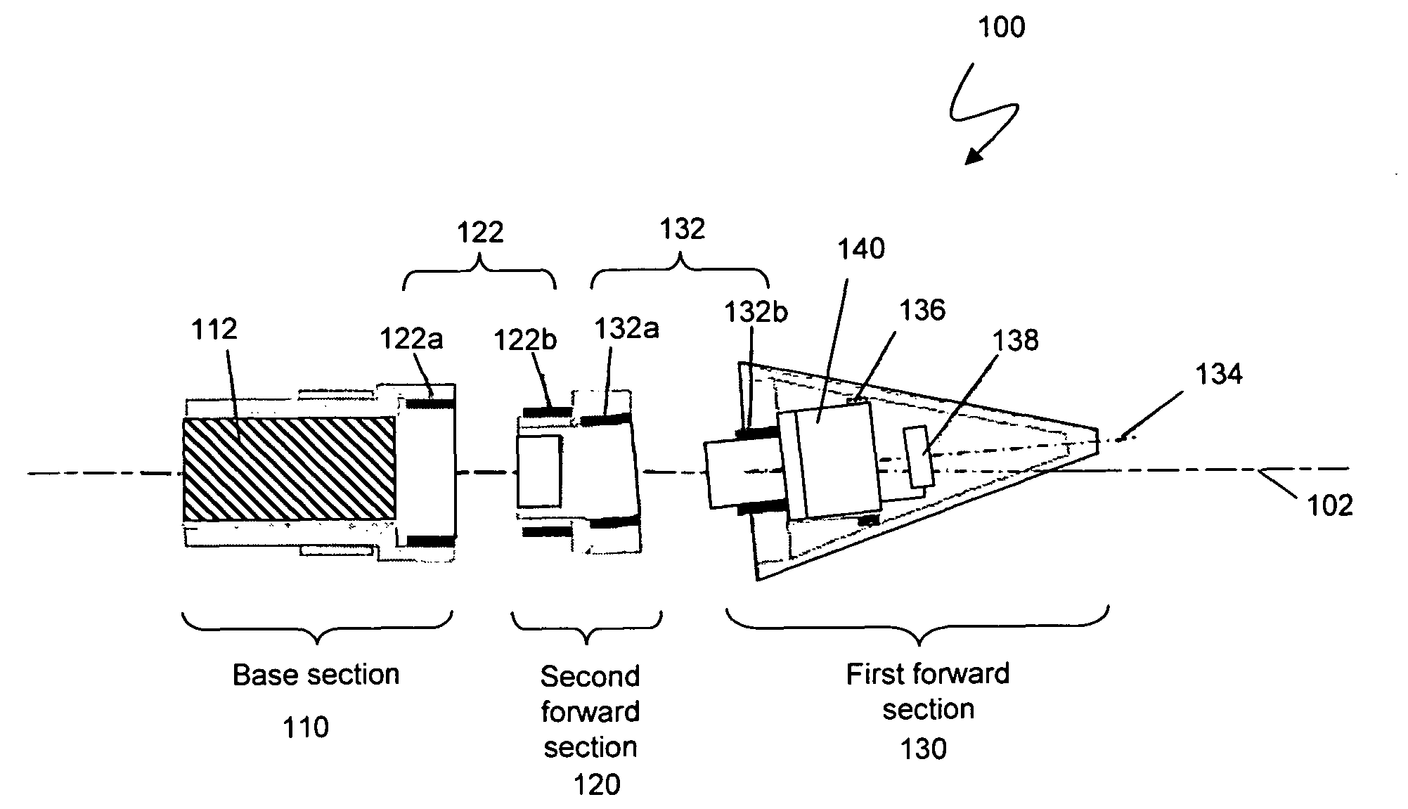
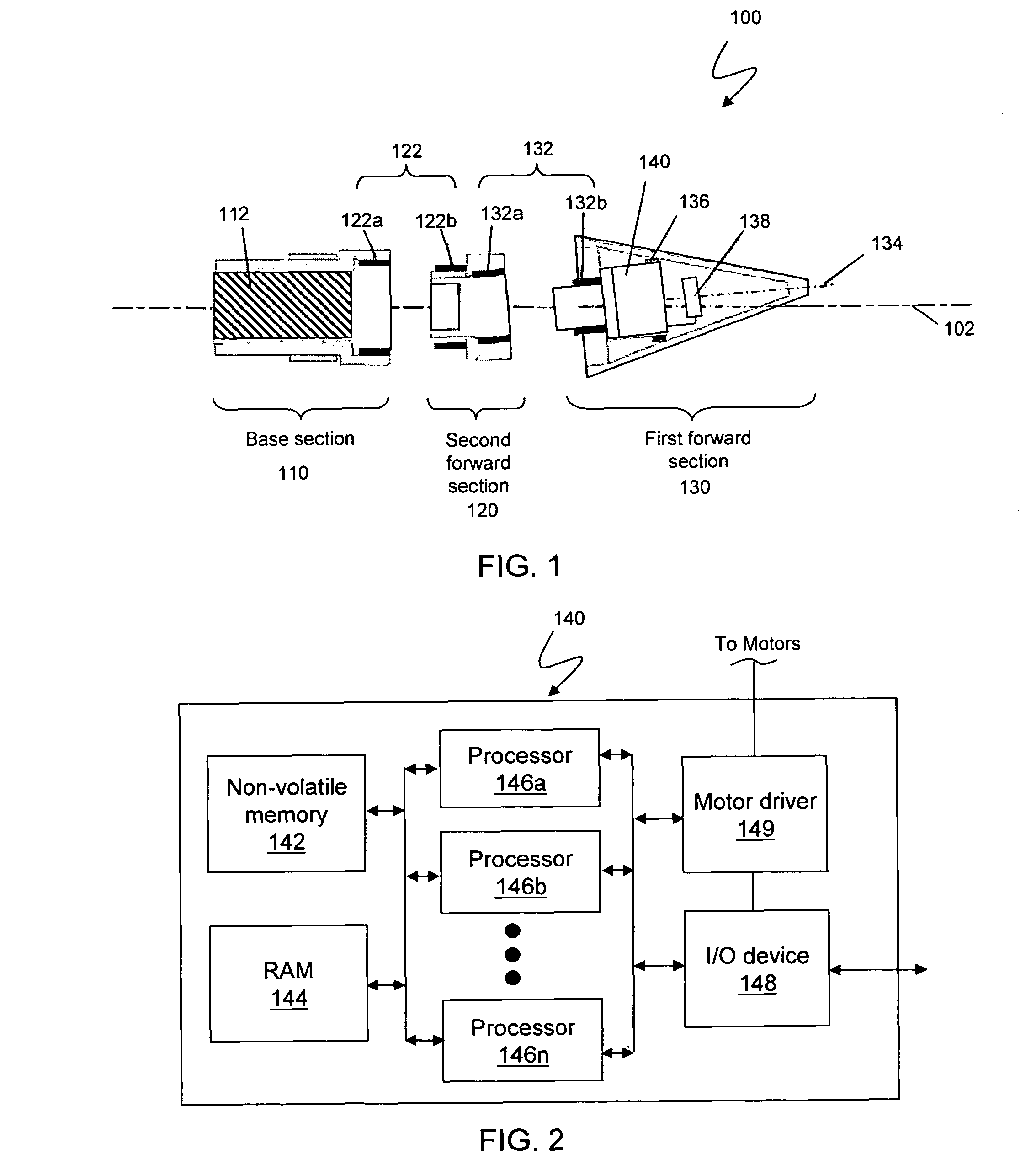
[0025]FIG. 1 illustrates an embodiment of a Reconfigurable Nose Control System (RNCS) 100 according to the system described herein. The RNCS 100 may include three sections: a first forward section 130, a second forward section 120 and a base section 110. The base section 110 may interface with a projectile body and include a fuze volume 112 to interface with fuze threads of the projectile body. The base section 110 and the second forward section 120 may include a Roll Motor Generator (RMG) 122, that functions as discussed elsewhere herein and may include other components as part of a roll motor generator assembly. The first forward section 130 ...


PUM


Abstract

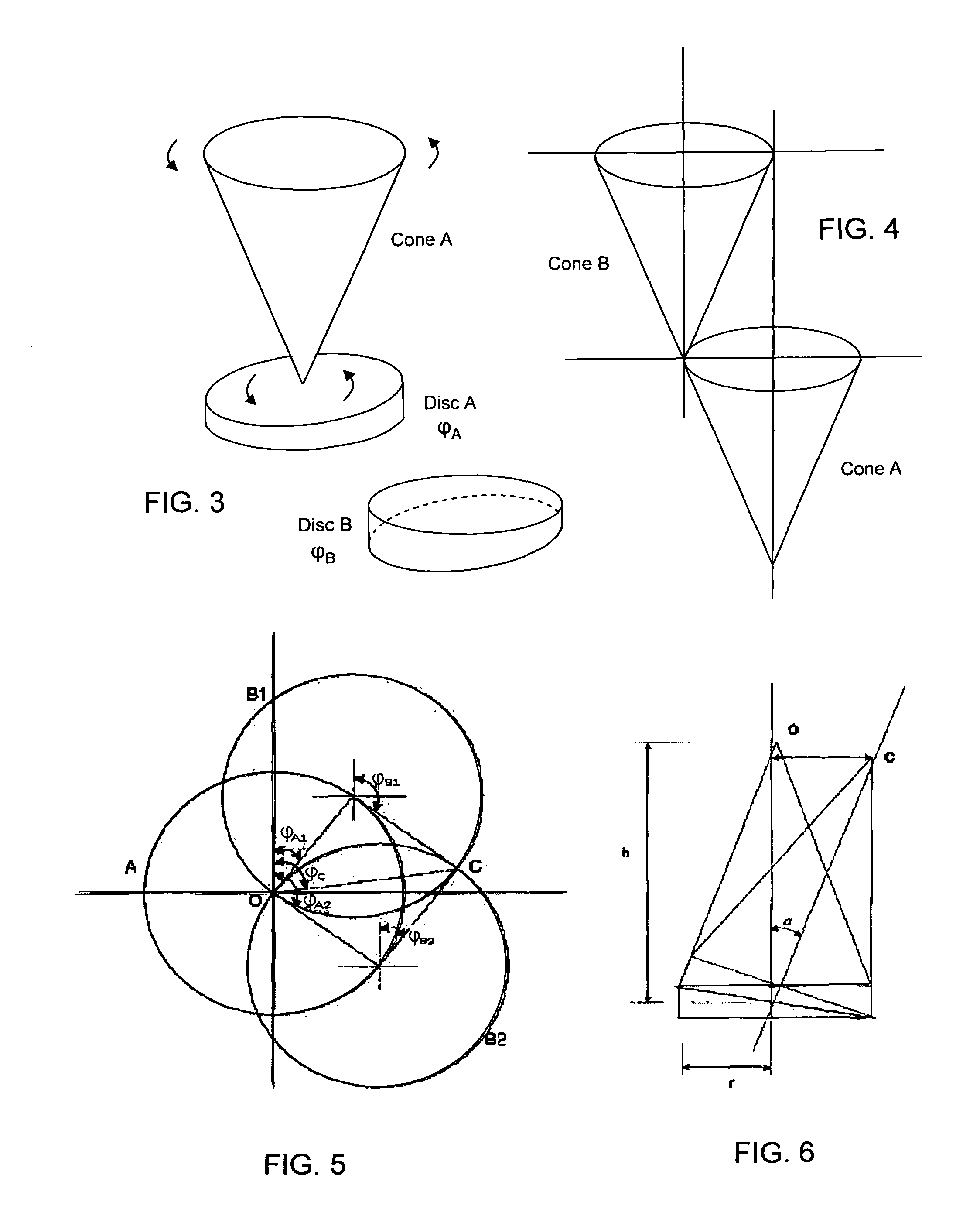
A Reconfigurable Nose Control System (RNCS) is designed to adjust the flight path of spin-stabilized artillery projectiles. The RNCS uses the surface of a projectile nose cone as a trim tab. The nose cone may be despun by the action of aerodynamic surfaces, to zero spin relative to earth fixed coordinates using local air flow, and deflected by a simple rotary motion of a Divert Motor about the longitudinal axis of the projectile. A forward section of the nose cone having an ogive is mounted at an angle to the longitudinal axis of the projectile, forming an axial offset of an axis of the forward section with respect to the longitudinal axis of the projectile. Another section of the nose cone includes another motor, the Roll Generator Motor, that is rotationally decoupled from the forward section and rotates the deflected forward section so that its axis may be pointed in any direction within its range of motion. Accordingly, deflection and direction of the forward section may be modulated by combined action of the motors during flight of the projectile.

Description

TECHNICAL FIELD[0001]This application is directed to the field of ballistics and, more particularly, to projectile trajectory control.BACKGROUND OF THE INVENTION[0002]Spin stabilized artillery projectiles are gyroscopically stabilized, spinning rapidly about the projectile's longitudinal axis resulting from the action of the rifling during the launch sequence. In free flight after muzzle exit, aerodynamic forces act on the projectile body, producing a complex epicyclic motion of nutation and precession throughout the trajectory that may affect, and otherwise interfere with, a desired trajectory of the projectile.[0003]As the range capability of artillery weapons and ammunition grows, accuracy and precision of delivery become increasingly important. Total delivery errors for standard, unguided 155 mm artillery projectiles, including all error sources, can exceed 300 meters at 30 km, while a point target size may be less than ten square meters. In such a case, the probability of hitti...

Claims


Application Information

Patent Timeline
Patent Type & Authority Patents(United States)
IPC IPC(8): G06F19/00
CPCF41G7/346F42B15/01F42B10/62F41G7/36
Inventor JENKINS, DENNIS HYATTBYRNE, JIMCHRISTIANA, JOHNFRANZ, PAULKELLY, TOM
Owner SIMMONDS PRECISION PRODS
Why Eureka
Try Eureka