Method and apparatus for beverage extraction with improved gas cylinder access

a technology of gas cylinders and beverage extraction, which is applied in the direction of liquid transferring devices, functional valve types, transportation and packaging, etc., can solve the problems of air or other potentially damaging gasses or liquids entering the bottle, and achieve the effect of little or no effect on beverage quality

Active Publication Date: 2015-09-15
CORAVIN
View PDF60 Cites 8 Cited by
  • Summary
  • Abstract
  • Description
  • Claims
  • Application Information

AI Technical Summary

Benefits of technology

[0003]One or more embodiments in accordance with aspects of the invention allow a user to withdraw or otherwise extract a beverage, such as wine, from within a container that is sealed by a cork, plug, elastomeric septum or other closure without removing the closure. In some cases, removal of liquid from such a container may be performed one or more times, yet the closure may remain in place during and after each beverage extraction to maintain a seal for the container. Thus, the beverage may be dispensed from the bottle multiple times and stored for extended periods between each extraction with little or no effect on beverage quality. In some embodiments, little or no gas, such as air, which is reactive with the beverage may be introduced into the container either during or after extraction of beverage from within the container. Thus, in some embodiments, a user may withdraw wine from a wine bottle without removal of, or damage to, the cork, and without allowing air or other potentially damaging gasses or liquids entry into the bottle. However, not all embodiments require the ability to remove an extraction device from a cork or other closure such that the closure reseals the bottle.
[0006]In another aspect of the invention, a fluid pressure regulator includes a first stage valve arranged to open and close a fluid flow path to control flow of fluid through the valve. The first stage valve may include a first valve body defining a valve chamber having an outlet opening and an inlet opening, a first valve gasket arranged in the valve chamber at the outlet opening, a first valve ball movable in the valve chamber to contact the first valve gasket and close the outlet opening, and a gasket retainer in the valve chamber and stationary relative to the first valve body arranged to hold the first valve gasket at the outlet opening. A first stage piston may be arranged for movement to move the first valve ball relative to the outlet opening and thereby open and close the first stage valve, and a regulator body may define a piston chamber in which the first stage piston is movable and may house the valve chamber. In one embodiment, the gasket retainer may include a cylindrical shell portion and an inwardly extending flange at a gasket end of the retainer arranged to contact the first valve gasket. The flange may have an annular shape and taper inwardly from the cylindrical shell portion. The first valve gasket may be arranged to deform with contact with the first valve ball, and the gasket retainer may be arranged in the valve chamber to restrict movement of the gasket due to deformation of the gasket. For example, the gasket retainer may be arranged to restrict movement of the gasket so that the gasket prevents contact of the first valve ball with the first valve body near the outlet opening. This arrangement may help prevent contact of a metal valve ball with a metal valve body, thereby reducing wear.
[0007]In one embodiment, the valve piston includes a depressor to contact and move the valve ball to open / close the valve, and the depressor may have a rigid, convex contact surface arranged to contact the first valve ball. This arrangement may help prevent the valve ball from following a same track during opening and closing movement, thus more evenly wearing the valve ball, gasket and / or depressor and / or allowing the valve to open and close to regulate pressure with reduced chattering or hammering of the valve ball.

Problems solved by technology

Thus, in some embodiments, a user may withdraw wine from a wine bottle without removal of, or damage to, the cork, and without allowing air or other potentially damaging gasses or liquids entry into the bottle.
However, not all embodiments require the ability to remove an extraction device from a cork or other closure such that the closure reseals the bottle.

Method used


Image

  • Method and apparatus for beverage extraction with improved gas cylinder access
  • Method and apparatus for beverage extraction with improved gas cylinder access
  • Method and apparatus for beverage extraction with improved gas cylinder access

Examples


Embodiment Construction

[0027]Aspects of the invention are described below with reference to illustrative embodiments, but it should be understood that aspects of the invention are not to be construed narrowly in view of the specific embodiments described. Thus, aspects of the invention are not limited to the embodiments described herein. It should also be understood that various aspects of the invention may be used alone and / or in any suitable combination with each other, and thus various embodiments should not be interpreted as requiring any particular combination or combinations of features. Instead, one or more features of the embodiments described may be combined with any other suitable features of other embodiments.

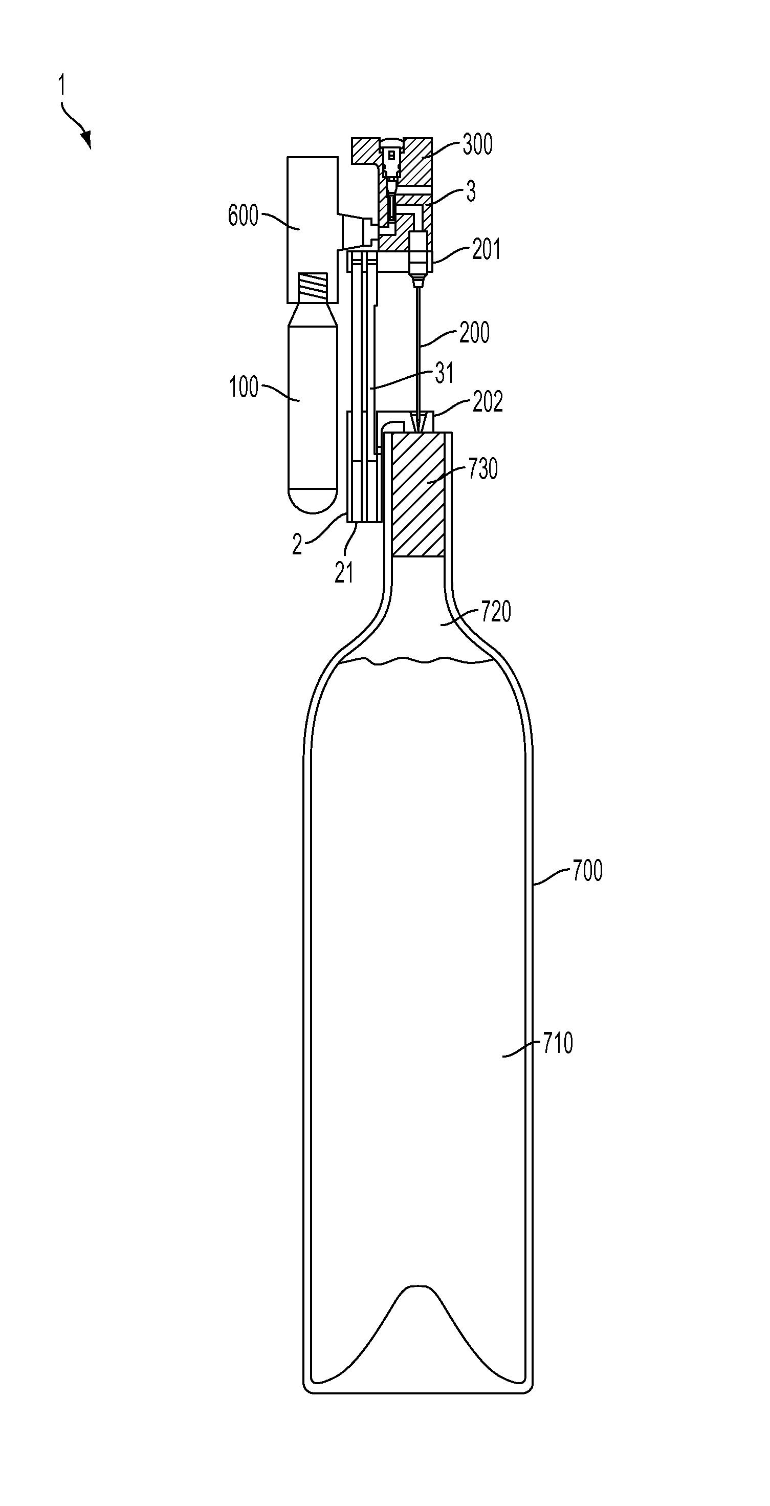
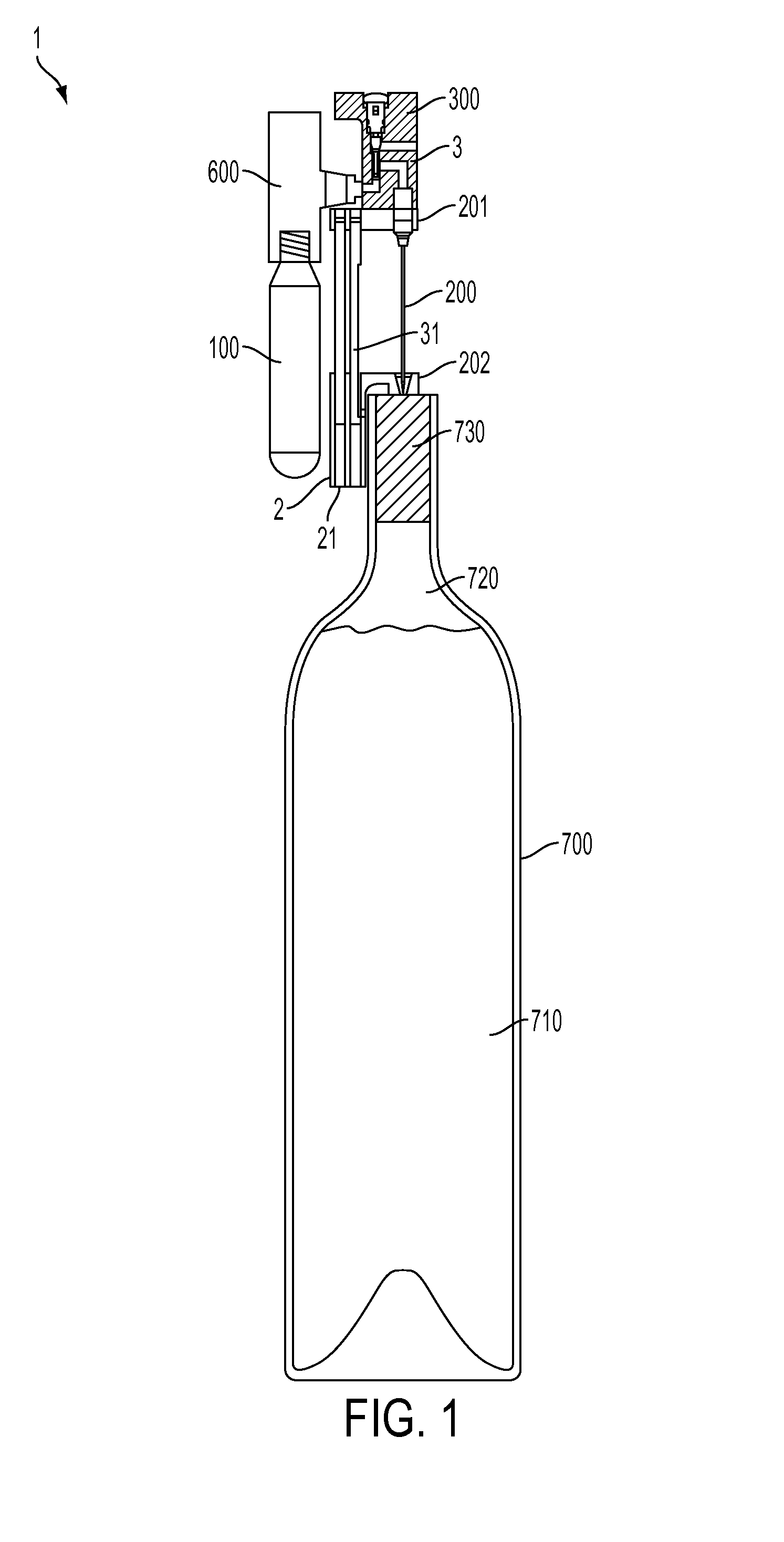
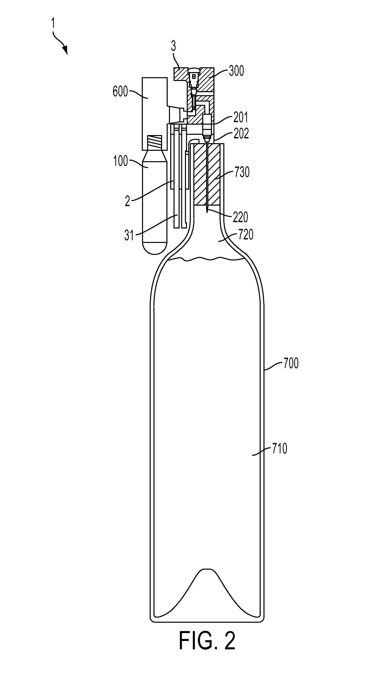
[0028]FIGS. 1-4 show schematic views of one embodiment of a beverage extraction device 1 that may incorporate one or more aspects of the invention. This illustrative system 1 includes a body 3 with an attached pressurized source of gas 100 (such as a compressed gas cylinder) that provides ...


PUM


Abstract

Devices and methods for extracting a beverage from a container, such as a wine bottle. Beverage can be extracted from a container by inserting a needle through a container closure, such as a cork, delivering pressurized gas into the container via the needle, and dispensing beverage from the container via the needle. A pressure regulator may control a pressure of gas introduced into the container, and a lance used to pierce a pressurized gas cylinder may include a leading face arranged to reliably pierce a cylinder closure. The regulator may include valve features to reduce valve chatter or hammering and provide a more reliable pressure seal.

Description

CROSS REFERENCE TO RELATED APPLICATIONS[0001]This application claims the benefit of U.S. patent application Ser. No. 61 / 835,114, filed Jun. 14, 2013, which is incorporated herein by reference in its entirety.BACKGROUND OF INVENTION[0002]This invention relates generally to accessing pressurized gas cylinders.SUMMARY OF INVENTION[0003]One or more embodiments in accordance with aspects of the invention allow a user to withdraw or otherwise extract a beverage, such as wine, from within a container that is sealed by a cork, plug, elastomeric septum or other closure without removing the closure. In some cases, removal of liquid from such a container may be performed one or more times, yet the closure may remain in place during and after each beverage extraction to maintain a seal for the container. Thus, the beverage may be dispensed from the bottle multiple times and stored for extended periods between each extraction with little or no effect on beverage quality. In some embodiments, lit...

Claims


Application Information

Patent Timeline
Patent Type & Authority Patents(United States)
IPC IPC(8): B67D7/00B67D1/00B67D1/08F16K17/06B67D1/04F16K17/04
CPCB67D1/0809B67D1/0004B67D1/0418B67D1/0885F16K17/0406F16K17/065Y10T137/7838Y10T137/7922Y10T137/7904B67D1/0412
Inventor RIDER, MIKEDERUNTZ, OTTOWING, LEE KA
Owner CORAVIN
Why Eureka
Try Eureka