Attaching method of fuel rail assembly for direct-injection engine

a technology of direct injection and assembly, which is applied in the direction of fuel injection apparatus, charge feed system, metal-working apparatus, etc., can solve the problems of improper interference with the cylinder head, difficulty in securing the fuel rail assembly relative to the cylinder head, and difficulty in securing the fuel rail and the plural fuel injectors together, so as to prevent any deterioration of the fuel seal

Inactive Publication Date: 2015-09-15
MAZDA MOTOR CORP
View PDF14 Cites 5 Cited by
  • Summary
  • Abstract
  • Description
  • Claims
  • Application Information

AI Technical Summary

Benefits of technology

[0011]An object of the present invention is to provide an attaching method of a fuel rail assembly for a direct-injection engine which can prevent any deterioration of the fuel seal which may be caused by the positional difference (error) of the fuel injector when the fuel rail assembly is assembled.
[0013]According to the above-described attaching method of a fuel rail assembly for a direct-injection engine, in the press inserting step, the respective spring members can generate the compressive reaction forces substantially equally, any situation where the compressive reaction force of any specified spring member may increase greatly compared with the other spring members can be properly restrained, so that the frictional force between the holding ring and the head-side seating portion can be suppressed below the reaction force of the base-end-portion seal ring member occurring in the perpendicular direction to the axial center of the fuel injector. Thereby, the appropriate position adjustment of the holding ring can be ensured, any improper decrease of the face pressure in the peripheral direction between the base-end-portion seal ring member provided at the cylindrical body portion and the cup portion can be prevented. Consequently, any deterioration of the fuel seal which may be caused by the positional difference (error) of the fuel injector can be prevented.
[0014]According to an embodiment of the present invention, the fastening step comprises a two-stage fastening with a fasting apparatus having plural fastening heads which correspond to plural fastening members to fasten the plural boss portions respectively, the two-stage fastening being configured such that a fastening torque of the plural fastening heads is increased up to a first torque value in a first state and then the fastening torque of the plural fastening heads is increased up to a second torque value which is greater than the first torque value. Thereby, the fuel rail assembly can be fastened concurrently, it can be prevented that the restraint of the holding ring occurs at a specified fuel injector in an early stage in the fastening step, and the positional difference (error) of the fuel injector can be prevented, thereby further preventing the deterioration of the fuel seal.

Problems solved by technology

Therefore, there is a concern that a small-diameter cylindrical portion at a tip portion of the fuel injector may not be correctly positioned in its injector-insertion hole, so that the small-diameter cylindrical portion of the fuel injector may interfere with the cylinder head improperly.
The attaching method of a fuel rail assembly disclosed in the above-described patent document has a concern that even if the fuel injector is adjusted at a proper position in the stage of moving toward the cylinder head, the fuel rail assembly may not be effectively fastened relative to the cylinder head due to its structure when the small-diameter cylindrical portion of the fuel injector is pressed and inserted into the injector-insertion hole.
First, it may be difficult to press the fuel rail and the plural fuel injectors together against the cylinder head by fastening the plural boss portions provided at the fuel rail with the bolts.
Secondly, it may be difficult to align the axial center of the fuel injector with the axial center of the injector-insertion hole.
That is, a processing error of the cup portions and a processing error of the injector-insertion holes may be accumulated complexly, so that an improper difference in position between the axial center of the fuel injector inserted into the cup portion and the axial center of the injector-insertion hole may occur.
However, since the axial center of the fuel injector is restricted by the injector-insertion hole via the base-end-portion seal ring member, the difference in position between the fuel injector and the injector-insertion hole may cause a slant of the axial center of the fuel injector relative to the axial center of the injector-insertion hole.
In a case in which the axial-center position of a specified fuel injector is restricted with its slating toward a certain direction in the press inserting step, if the fuel rail is compulsorily moved toward the cylinder head prior to completion of this step, the difference (error) in the axial center between the fuel injector and the cup portion increases.
Thus, there is a concern that the axial-center difference (error) of the above-described specified fuel injector may deteriorate extremely more than that of the other fuel injector.
Additionally, in a case in which the timings of fastening bolts improperly vary in a fastening step after the press inserting step, there is a concern that the difference (error) in the axial center between the fuel injector and the cup portion may further increase.
Herein, while it may be considered that a pressing force of the rail member is cancelled once in a previous step prior to the fastening step, this cancelation merely causes a temporary releasing of the biasing force of the spring member, so that there is a concern that the axial-center difference (error) of the fuel injector may occur again when the re-press inserting step or the fastening step restart.
Therefore, when the positional difference between the fuel injector and the cup portion is improperly large, there exists a portion where a face pressure in a peripheral face between the base-end-portion seal ring member and the cup portion decreases, in particular, the hardness of the base-end-portion seal ring member increases in a cold engine-operational state.
Thus, there is a concern that the fuel seal may deteriorate at the portion with the decreased face pressure.

Method used


Image

  • Attaching method of fuel rail assembly for direct-injection engine
  • Attaching method of fuel rail assembly for direct-injection engine
  • Attaching method of fuel rail assembly for direct-injection engine

Examples


Embodiment Construction

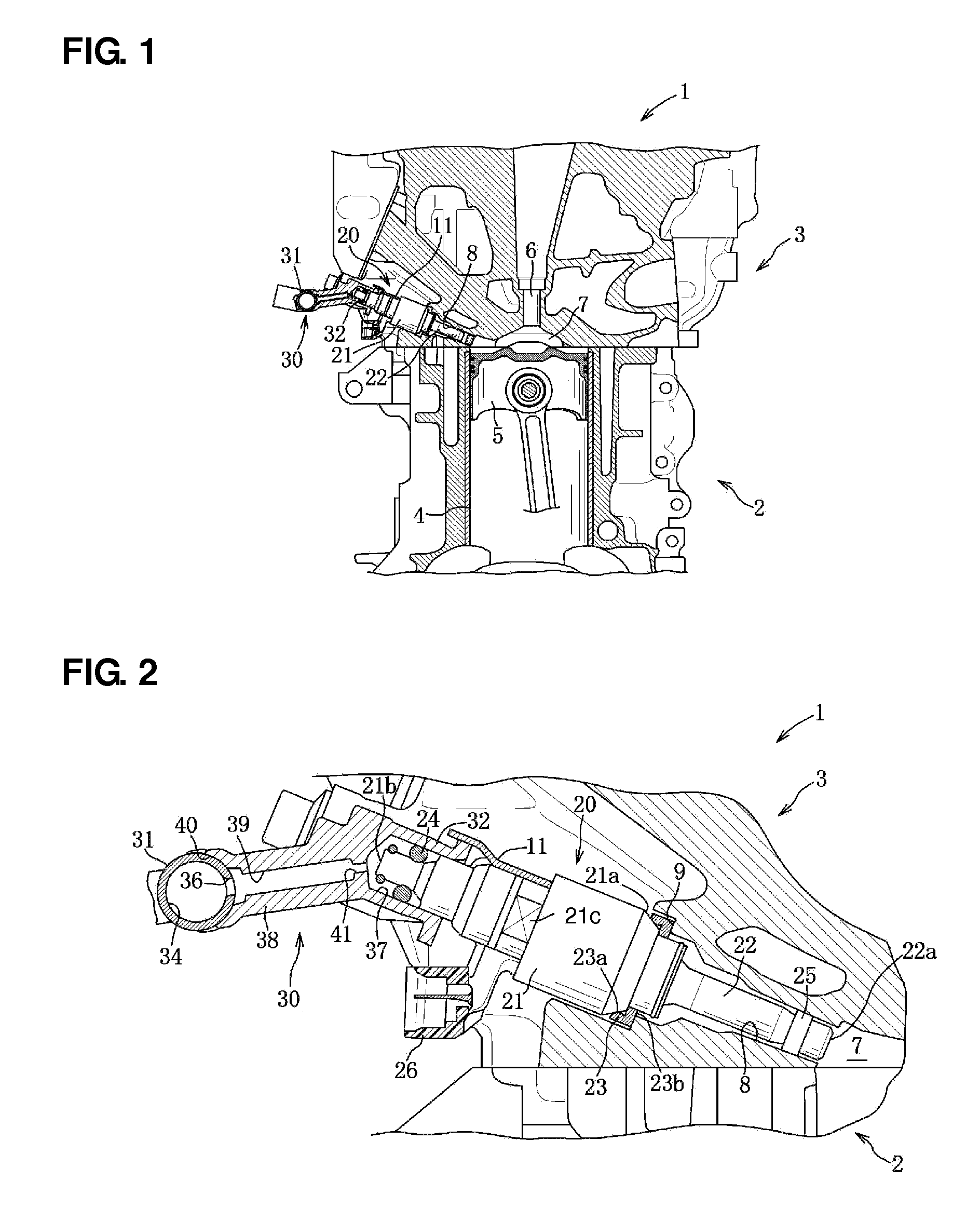
[0026]Hereinafter, a preferred embodiment of the present invention will be described referring to FIGS. 1-9.

[0027]A direct-injection engine 1 is an inline four-cylinder engine equipped with four cylinders arranged in line along a direction of a crankshaft (not illustrated) as shown in FIG. 4. The engine 1 comprises a cylinder block 2, a cylinder head 3, and others. The cylinder block 2 comprises a cylinder liner 4, a piston 5 reciprocating vertically in the cylinder liner 4, and others for each cylinder.

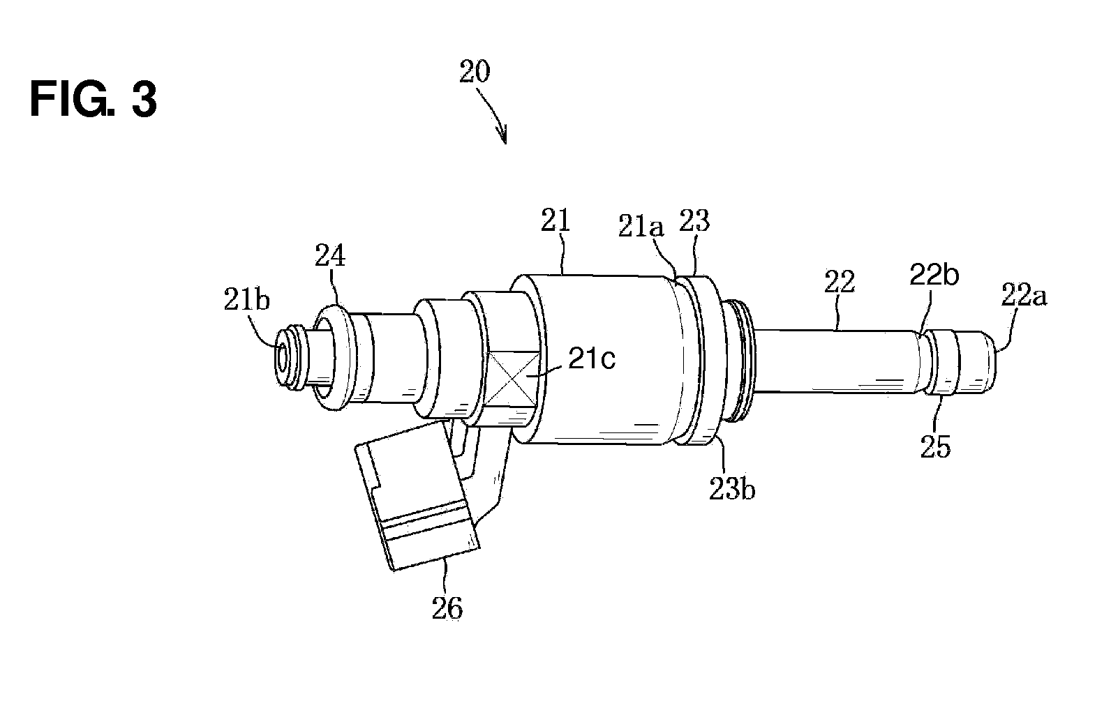
[0028]The cylinder head 3 comprises two intake ports (not illustrated), two exhaust ports (not illustrated), intake and exhaust valves (not illustrated) to open or close these ports, an ignition plug 6, a fuel injector 20, and others for each cylinder. An upper face of the piston 5 positioned at a top dead center and a pent roof-shaped lower face of the cylinder head 3 form together a combustion chamber 7 for each cylinder. The engine 1 introduces intake air into the combustion chamb...


PUM

PropertyMeasurementUnit
pressureaaaaaaaaaa
elastic forceaaaaaaaaaa

Abstract

An injector comprises a cylindrical body portion, a holding ring capable of centering an axial center of the injector, and a small-diameter cylindrical portion. There are provided an assembly forming step of forming a fuel rail assembly by inserting the injectors into respective cup portions via spring members for reaction force absorption, a press inserting step of pressing and inserting respective tip-side portions of the injectors by pressing pressure-receiving portions such that the respective spring members are compressed up to a middle compressive state thereof with a pressing movable apparatus which is capable of pressing the pressure-receiving portions of a fuel rail via respective pressing springs, and a fastening step of fastening plural boss portions concurrently to a cylinder head in a state in which a pressing force of the press inserting step is maintained.

Description

BACKGROUND OF THE INVENTION[0001]The present invention relates to an attaching method of a fuel rail assembly for a direct-injection engine.[0002]Conventionally, a direct-injection engine which injects fuel directly through a fuel injector projecting into a combustion chamber of the engine is known in vehicles, such as automotive vehicles. In an inline type of direct-injection engine equipped with plural cylinders arranged in line, high-pressure fuel is supplied to respective fuel injectors for the plural cylinders via a fuel rail. This fuel rail comprises a rail member extending straightly along a cylinder-line direction to supply the fuel therethrough, plural cup portions to deliver the fuel from the rail member to the respective fuel injectors, and plural boss portions to fasten the fuel rail to a cylinder head thereby, which delivers the fuel from a fuel pump of the engine to the respective fuel injectors for the plural cylinders.[0003]When the fuel injectors are attached to the...

Claims


Application Information

Patent Timeline
Patent Type & Authority Patents(United States)
IPC IPC(8): F02M61/14F02M55/02
CPCF02M55/025F02M61/14F02M2200/857Y10T29/49231
Inventor TAKASAKI, NOBUAKIYAMASHITA, SHIGEKIUOTANI, YUZOMIYATA, TAKASHI
Owner MAZDA MOTOR CORP
Why Eureka
Try Eureka