Front light and method for producing same, reflective display device provided with front light, and electronic equipment provided with reflective display device

a reflective display device and front light technology, applied in the direction of optical light guides, instruments, optics, etc., can solve the problems of deterioration of the display device the difficulty of the reflective display device in carrying out high-contrast display, and achieve the effect of high-contrast display

Inactive Publication Date: 2015-09-15
SHARP KK
View PDF12 Cites 4 Cited by
  • Summary
  • Abstract
  • Description
  • Claims
  • Application Information

AI Technical Summary

Benefits of technology

[0029]According to the front light of the embodiment of the present invention, since the light reflective layers are completely covered by the dark layers in the respective plurality of dots, it is possible for the dark layers to absorb (i) light which has leaked from the light guide plate toward a user and (ii) surrounding light which enters the front light. That is, since the light reflective layers are not exposed in side surfaces of the respective plurality of dots, it is possible to prevent (i) the light which has leaked from the light guide plate toward a user and (ii) the surrounding light which enters the front light, from being reflected by the light reflective layers to exit toward the user. Therefore, by employing the front light of the embodiment of the present invention, a reflective display device can carry out high-contrast display even when the reflective display device is viewed from any angles.
[0030]According to the method, of the embodiment of the present invention, of producing a front light, it is possible to provide a front light which enables a reflective display device to carry out high-contrast display even when the reflective display device is viewed from any angles.

Problems solved by technology

This causes a deterioration in display of the reflective display device 30.
This makes it difficult for the reflective display device to carry out high-contrast display.

Method used


Image

  • Front light and method for producing same, reflective display device provided with front light, and electronic equipment provided with reflective display device
  • Front light and method for producing same, reflective display device provided with front light, and electronic equipment provided with reflective display device
  • Front light and method for producing same, reflective display device provided with front light, and electronic equipment provided with reflective display device

Examples


embodiment

[0056][Embodiment]

[0057](Configuration of Reflective Display Device 10)

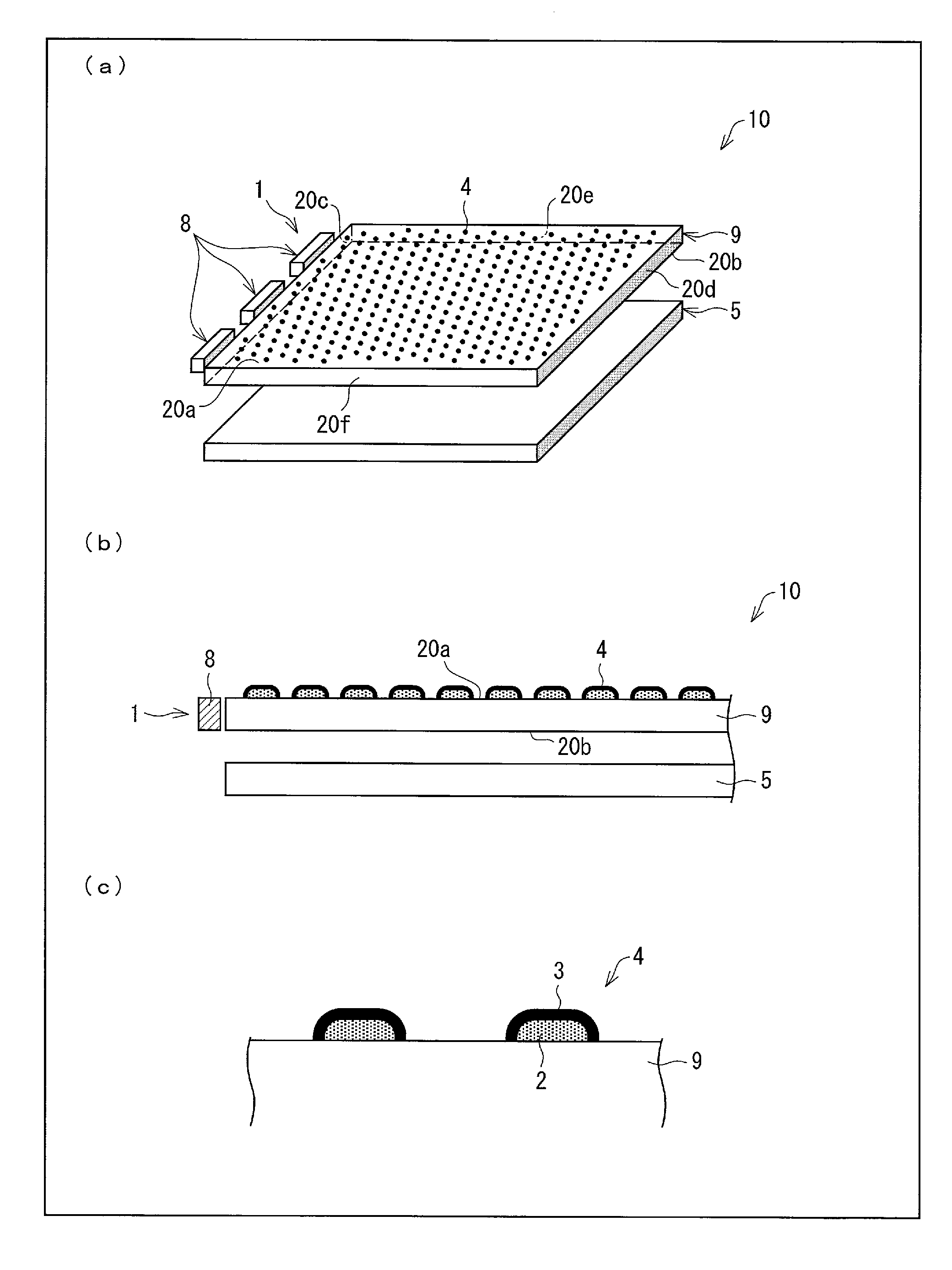
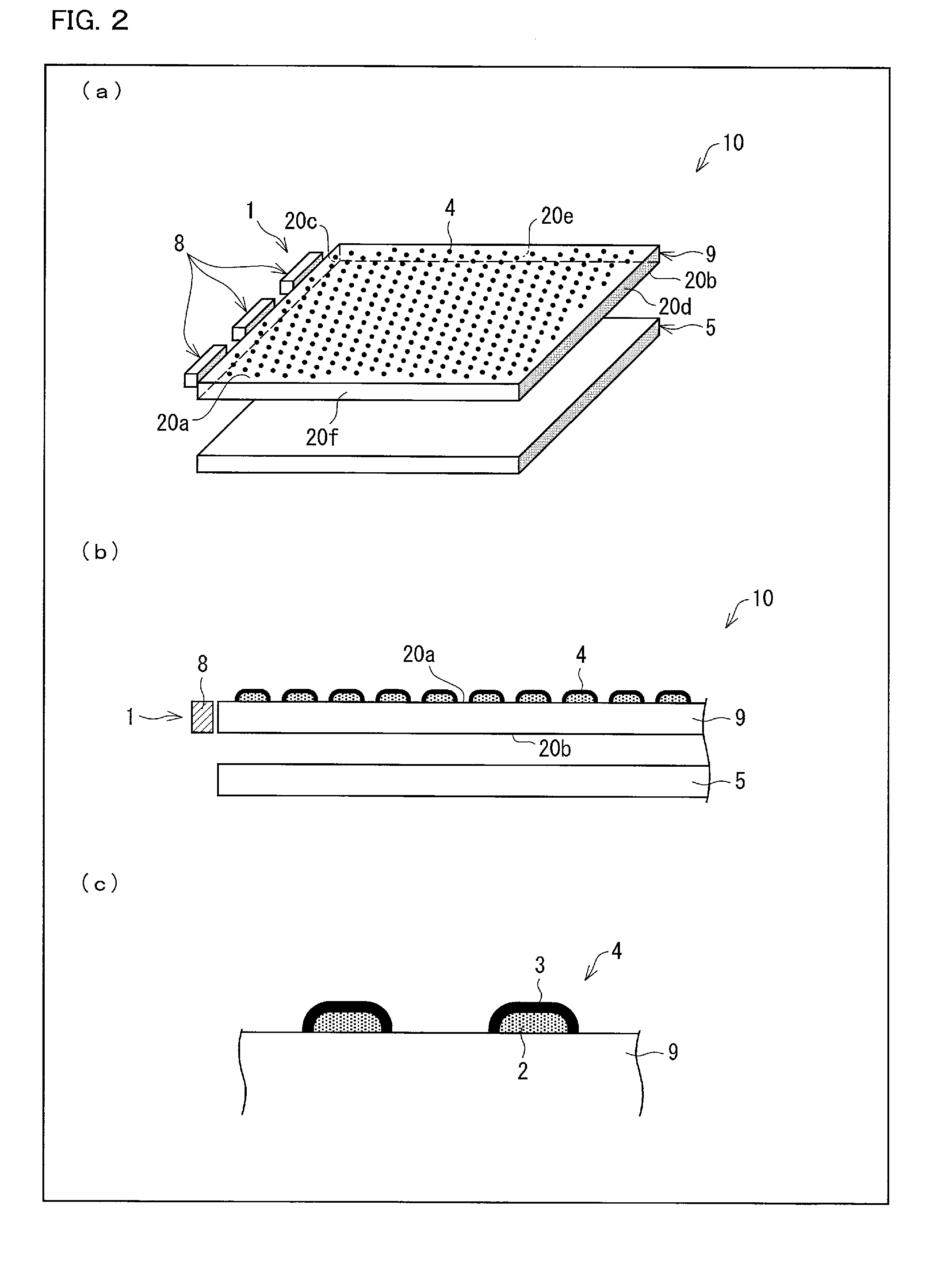
[0058]A configuration of a reflective display device that includes a front light of the embodiment of the present invention will be described with reference to FIG. 2. (a) of FIG. 2 is a perspective view illustrating a reflective display device 10 in accordance with the embodiment of the present invention. (b) of FIG. 2 is a cross-sectional view illustrating the reflective display device 10. (c) of FIG. 2 is an enlarged view illustrating a cross section of dots 4 on a light guide plate 9 in accordance with the embodiment of the present invention.

[0059]As illustrated in (a) of FIG. 2, the reflective display device 10 includes (i) a display panel 5, and (ii) a front light 1 which is provided on a side of the display device 5, on which side a user views an image on the display panel 5 (hereinafter referred to as a user side). The front light 1 includes (i) the light guide plate 9, and (ii) a light source(s) 8 which ...

modification 1

[0093](Modification 1)

[0094]Dots 4 can be formed not only by use of the printing method but also by use of, for example, a photolithographic method. A front light 1, in which dots 4 are formed by use of the photolithographic method, will be described below with reference to FIGS. 7 and 8. (a) of FIG. 7 is a cross-sectional view illustrating a reflective display device 10 in accordance with Modification 1 of the present invention. (b) of FIG. 7 is an enlarged view illustrating a cross section of the dots 4 on a light guide plate 9 in accordance with Modification 1 of the present invention. (a) through (f) of FIG. 8 are views illustrating a process of forming the dots 4 by use of the photolithographic method.

[0095]Steps of the process will be described below. Note that, in the process, light reflective layers 2 are formed with use of a white resist ink, and dark layers 3 are formed with use of a black resist ink. Examples of the white resist ink include “White Color Solder Resist” man...

modification 2

[0101](Modification 2)

[0102]FIG. 9 is an enlarged view illustrating a cross section of dots 4 on a light guide plate 9 in accordance with Modification 2 of the present invention. As illustrated in FIG. 9, the dots 4 can be formed by (i) forming recesses in the light guide plate 9 in advance, (ii) filling the recesses with white ink so that light reflective layers 2 are formed in the respective recesses, and (iii) further applying black ink onto the light reflective layers 2 so that respective dark layers 3 are formed. The dots 4 thus formed less protrude from the light guide plate 9, as compared with a case where light reflective layers 2 and dark layers 3 are formed not in respective recesses which are formed in a light guide plate 9 but on the light guide plate 9. It is therefore possible to prevent the dots 4 from being exfoliated by being caught on something.


PUM

PropertyMeasurementUnit
angleaaaaaaaaaa
sizeaaaaaaaaaa
refractive indexaaaaaaaaaa

Abstract

A front light (1) includes a light source (8), a light guide plate (9), and a plurality of dots (4) that are provided on a surface of the light guide plate (9), which surface faces a light exit surface of the light guide plate (9). Each of the plurality of dots (4) includes (i) a light reflective layer (2) for reflecting light toward the light guide plate (9), and (ii) a dark layer (3) for absorbing light, the dark layer completely covering the light reflective layer (2) so as to be in contact with the light guide plate (9) without any gap between the light guide plate (9) and the dark layer (3).

Description

TECHNICAL FIELD[0001]The present invention relates to (i) a front light, (ii) a method of producing the front light, (iii) a reflective display device including the front light, and (iv) an electronic device including the reflective display device.BACKGROUND ART[0002]Under a dark environment where no surrounding light is present, a user cannot recognize display on a non-light emitting display device, such as a reflective liquid crystal display device, an electrophoretic display device or an electrowetting display device, which carries out the display while reflecting surrounding light such as outside light. In order to allow a user to recognize display under such a dark environment, some of such non-light emitting display devices include, above a front surface of a display panel, a front light which illuminates the display panel.[0003]A front light should have first and second properties below. The first property is that the front light itself is transparent so that display (a displ...

Claims


Application Information

Patent Timeline
Patent Type & Authority Patents(United States)
IPC IPC(8): F21V8/00G02F1/1335
CPCG02B6/0043G02B6/0055G02F2001/133616G02F1/133616
Inventor WATANABE, HISASHITERANISHI, TOMOKOMATSUOKA, TOSHIKINAKAHARA, TAKAHIROTOMOTOSHI, TAKUMASATOH, EIJINAKAMURA, KOHZOHNARUTAKI, YOHZOH
Owner SHARP KK
Why Eureka
Try Eureka