Converging substrate, electro-optic device, substrate for electro-optic device, projector, and electronic apparatus

a technology of electro-optic devices and substrates, applied in the direction of optics, color television details, instruments, etc., can solve the problems of reducing the efficiency of light utilization in the projection optical system, reducing contrast, and increasing the ray angle of light rays entering the liquid crystal layer, so as to achieve bright display, prevent the deterioration of the electro-optic device due to the irradiation of light rays, and increase the contrast

US7768707B2Inactive Publication Date: 2010-08-03SEIKO EPSON CORP
17 Cites 2 Cited by

Patent Information

Authority / Receiving Office
US · United States
Patent Type
Patents(United States)
Current Assignee / Owner
Publication Date
2010-08-03
Estimated Expiration
Not applicable · inactive patent

Smart Images

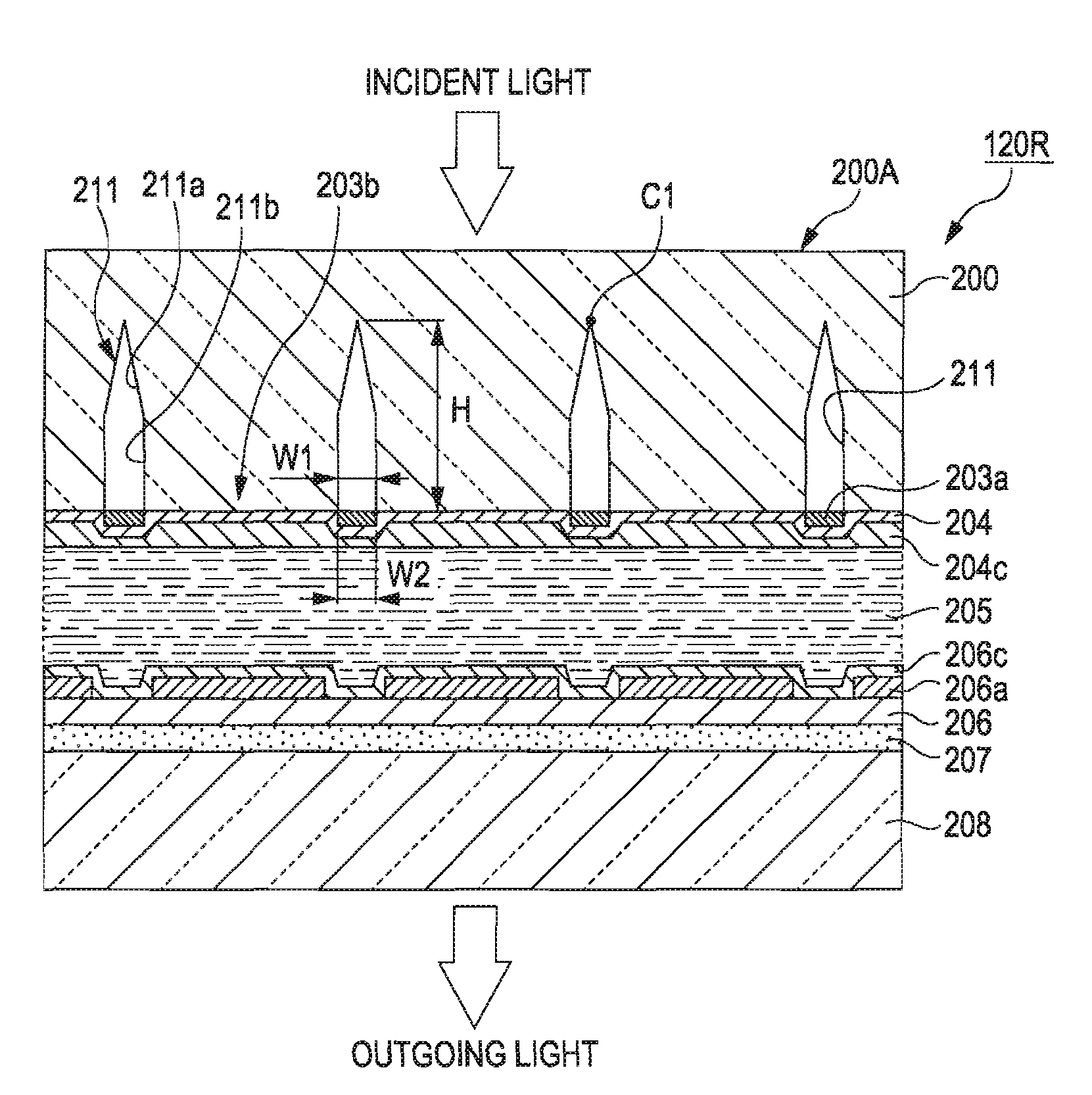
  • Figure 1
    Figure 1
  • Figure 2
    Figure 2
  • Figure 3
    Figure 3
Patent Text Reader

Abstract

An electro-optic device having a plurality of pixels arranged in a matrix pattern, including: a converging substrate formed of a transparent substrate having groove-shaped prism elements formed in an array pattern, wherein the prism elements are arranged along boundary areas of the pixels, wherein the prism elements each include a plurality of beveled portions arranged on side walls thereof in the direction of the thickness of the converging substrate, and wherein the inclination angle of the beveled portions arranged on an opening end side of each of the prism elements with respect to the normal line of the converging substrate on which the prism elements are formed is smaller than the inclination angle of the other beveled portions.
Need to check novelty before this filing date? Find Prior Art

Description

BACKGROUND

[0001] 1. Technical Field

[0002] Several aspects of the present invention relate to a converging substrate, an electro-optic device, a substrate for an electro-optic device, a projector, and an electronic apparatus.

[0003] 2. Related Art

[0004] An electro-optic device includes circuits for driving pixels in an image display area and, in particular, a liquid crystal device includes various wirings and switching devices such as TFT (Thin Film Transistor) Therefore, the ratio (aperture ratio) of an area from which. light rays actually go out (an area which contributes to a display) with respect to a pixel area is, for example, approximately 70%, and hence only the light amount corresponding to this aperture ratio is used for the display. Therefore, improvement of the efficiency for light utilization by providing microlenses corresponding to the respective pixels of the liquid crystal device and converging light rays supplied from a light source toward aperture areas of the pixels is...

Examples

Embodiment Construction

Projector

[0056]Referring now to the drawings, embodiments of the invention will be described.

[0057]FIG. 1 illustrates a schematic configuration of a projector according to an embodiment of the invention. As shown in FIG. 1, an extra-high pressure mercury lamp 101 as a light source supplies a light ray including red light as first-color light (hereinafter referred to as “R-light”), green light as second-color light (hereinafter referred to as “G-light”), and a blue light as third-color light (hereinafter referred to as “B-light”). An integrator 104 uniformizes distribution of illumination intensity of light rays supplied from the extra-high pressure mercury lamp 101. The light ray whose distribution of illumination intensity is uniformized by the integrator 104 is converted into a linear polarized light having a specific direction of oscillation, for example, into s-polarized light, by a polarized light converting element 105. The light converted into the S-polarized light enters an ...