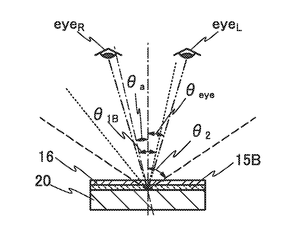
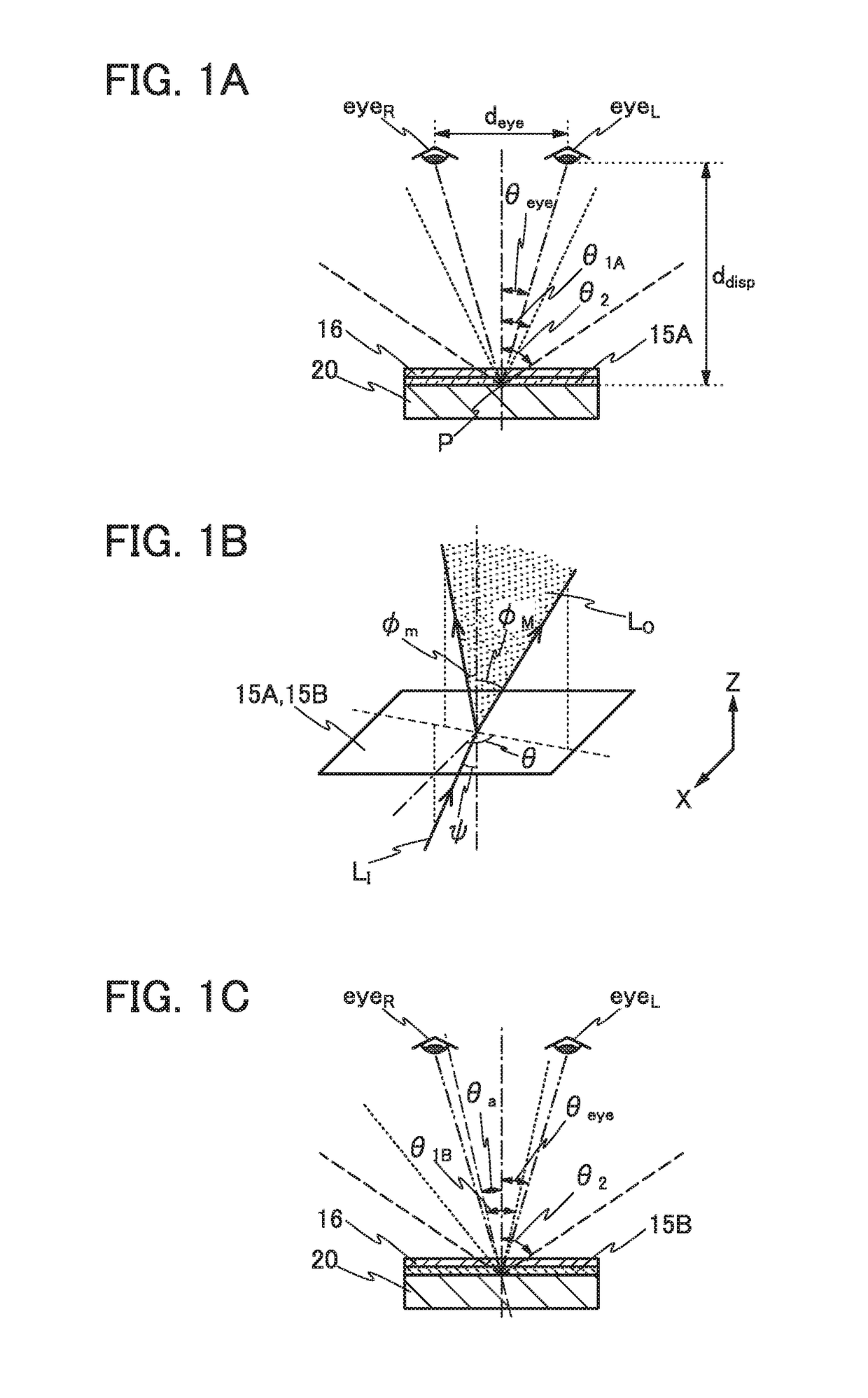
Display device
a display device and display technology, applied in non-linear optics, instruments, optics, etc., can solve the problems of power consumption, display device cracking in some cases, etc., and achieve the effect of improving display quality and high productivity
- Summary
- Abstract
- Description
- Claims
- Application Information
AI Technical Summary
Benefits of technology
Problems solved by technology
Method used
Image
Examples
embodiment 1
[0058]In this embodiment, a display device of one embodiment of the present invention is described.
[0059]In a display device of one embodiment of the present invention, a first display element that reflects visible light and a second display element that emits visible light are mixed.
[0060]The display device has a function of displaying an image utilizing one or both of first light reflected by the first display element and second light emitted from the second display element. Alternatively, the display device has a function of expressing gray scales by individually controlling the amount of the first light reflected by the first display element and the amount of the second light emitted from the second display element.
[0061]The display device preferably includes first pixels each of which produces gray levels by controlling the amount of light reflected by the first display element and second pixels each of which produces gray levels by controlling the amount of light emitted by th...
modification examples
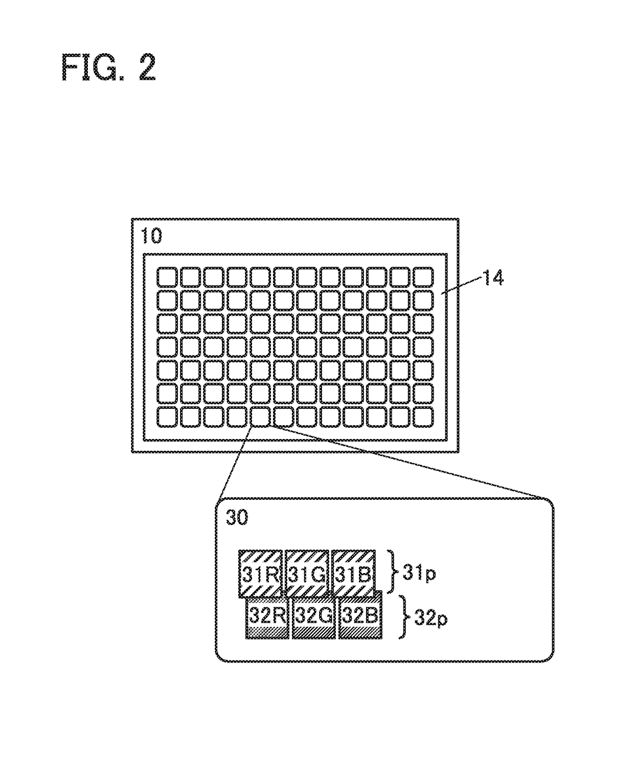
[0108]Although the example in which the first pixel 31p and the second pixel 32p each include display elements for three colors of red (R), green (G), and blue (B) is described above, one embodiment of the present invention is not limited thereto. A structure example different from the above will be described below.
[0109]FIGS. 4A to 4C and FIGS. 5A to 5C each illustrate a structure example of the pixel unit 30. Although schematic views corresponding to a mode (third mode) in which display is performed by driving both the first pixel 31p and the second pixel 32p are illustrated here, display can be performed using either the mode (first mode) in which display is performed with only reflected light by driving the first pixel 31p or the mode (second mode) in which display is performed with only emitted light (transmitted light) by driving the second pixel 32p, as in the above cases.
[0110]FIG. 4A illustrates an example in which the second pixel 32p includes a display element 32W that ex...
embodiment 2
[0129]In this embodiment, a display device of one embodiment of the present invention and a manufacturing method thereof will be described.
[0130]A display device of one embodiment of the present invention has a structure where a first display panel and a second display panel are bonded to each other with an adhesive layer therebetween. In the first display panel, first pixels that include reflective liquid crystal elements are provided. In the second display panel, second pixels that include light-emitting elements are provided. The reflective liquid crystal elements can produce gray levels by controlling the amount of reflected light. The light-emitting elements can produce gray levels by controlling the amount of light emission.
[0131]The display device can perform display by using only reflected light, display by using only light emitted from the light-emitting elements, and display by using both reflected light and light emitted from the light-emitting elements, for example.
[0132...
PUM
 Abstract
Description
Claims
Application Information
 - R&D
- Intellectual Property
- Life Sciences
- Materials
- Tech Scout
- Unparalleled Data Quality
- Higher Quality Content
- 60% Fewer Hallucinations
Browse by: Latest US Patents, China's latest patents, Technical Efficacy Thesaurus, Application Domain, Technology Topic, Popular Technical Reports.
© 2025 PatSnap. All rights reserved.Legal|Privacy policy|Modern Slavery Act Transparency Statement|Sitemap|About US| Contact US: help@patsnap.com


