Portable keying device and method

a keying device and portability technology, applied in the field of transacting terminals, can solve problems such as deleting security information, critical security issue, and tampering protection

Inactive Publication Date: 2015-09-15
HAND HELD PRODS
View PDF59 Cites 139 Cited by
  • Summary
  • Abstract
  • Description
  • Claims
  • Application Information

AI Technical Summary

Problems solved by technology

Because of the sensitive financial information being transmitted and received by these electronic terminals, security is a critical issue.
Another security issue relates to tamper protection.
In one approach, if the processor detects a downloading operation that may result in security information being compromised, the processor deletes the security information.
While the above described methods are effective in terms of preventing or monitoring tampering, there are problems associated with these methods.
These steps are inefficient, time consuming and costly.

Method used


Image

  • Portable keying device and method
  • Portable keying device and method
  • Portable keying device and method

Examples


second embodiment

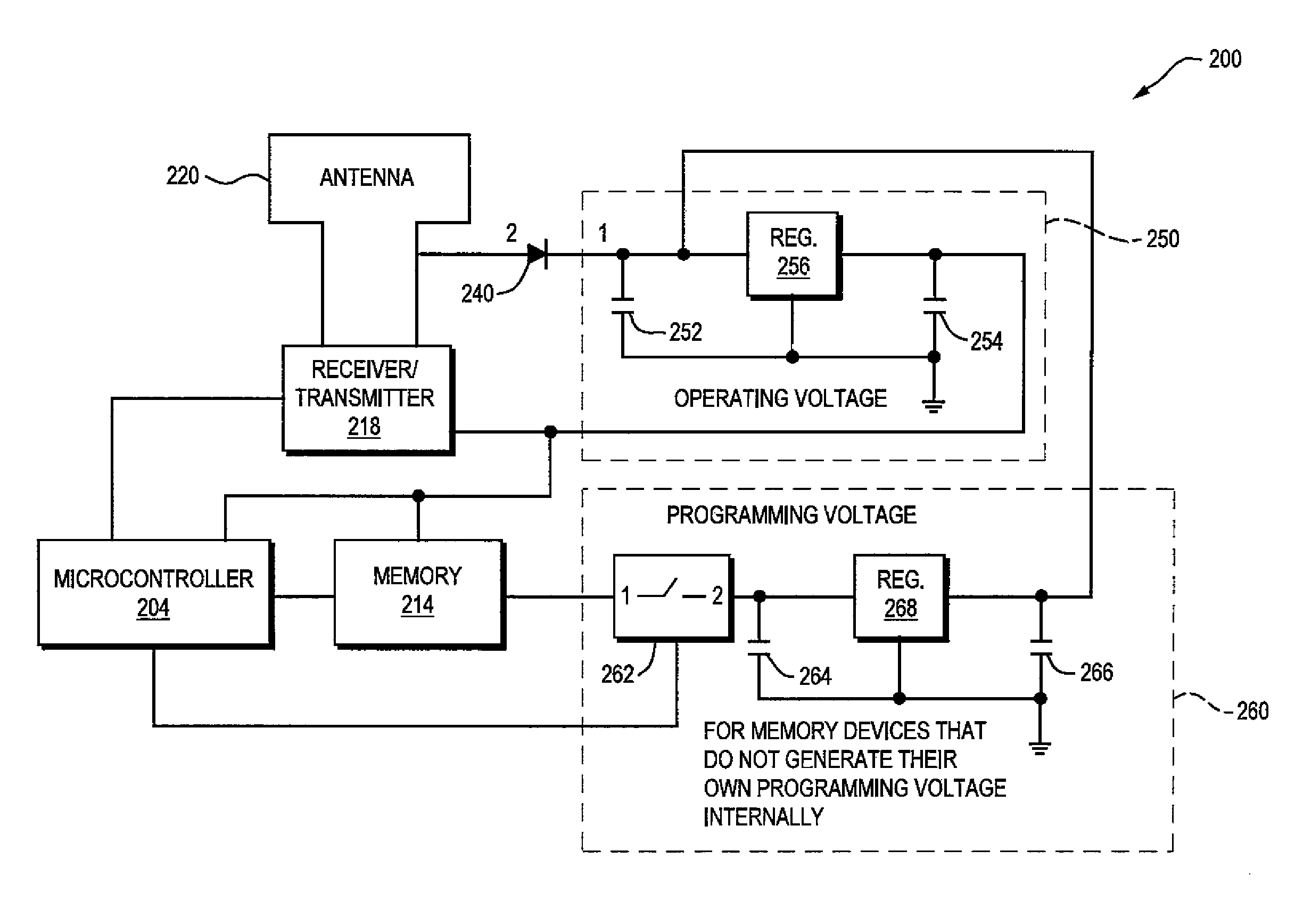
[0032]As embodied herein, and depicted in FIG. 5A, a diagrammatic depiction of electronic terminal 200 in accordance with the present invention is disclosed. In this embodiment, key memory 214 requires an external programming voltage. As described above, terminal 200 includes processor 204, key memory 214, transceiver 218 and antenna 220. In this example it is assumed that terminal 200 is boxed in a shipping container of some sort. Thus, terminal 200 is not connected to any external power supply. However, terminal 200 includes diode 240, normal operating voltage supply 250 and programming voltage supply 260. Normal operating voltage supply 250 includes capacitor 252, capacitor 254, and voltage regulator 256. Programming operating voltage supply 260 includes capacitor 262, capacitor 264, and voltage regulator 266. When portable device 100 transmits an RF signal to terminal 200, diode 240 rectifies the AC-RF signal and prevents any return signal from damaging the RF components. The re...

third embodiment

[0033]As embodied herein, and depicted in FIG. 6, a diagrammatic depiction of an electronic terminal in accordance with the present invention is disclosed. In this embodiment, battery 242 is included within terminal 200 to provide a normal operating voltage. Diode 240 is included to rectify the RF signal and prevent any return signals from damaging the RF components. Programming operating voltage supply 250 is included to provide programming voltage to key memory 214. Programming operating voltage supply 250 includes capacitor 254, capacitor 256, and voltage regulator 258. When portable device 100 transmits an RF signal to terminal 200, diode 240 rectifies the AC-RF signal. The resultant DC signal is used to charge up capacitors 254 and 256. Again, at the proper time, e.g. during step S308 (See FIG. 3), processor 204 activates switch 252 and supply 250 provides memory 214 with the programming voltage required to store the new encryption key therein.

fourth embodiment

[0034]As embodied herein, and depicted in FIG. 7, a diagrammatic depiction of an electronic terminal in accordance with the present invention is disclosed. In this embodiment, the required programming voltage is supplied internally. Battery 240 is included within terminal 200 to provide both the normal operating voltage and the programming voltage. In this embodiment battery 240 is coupled to programming voltage supply 250. Programming voltage supply 250 is identical to those depicted in FIG. 5A, FIG. 5B and FIG. 6. Since battery 240 supplies DC voltage to capacitors 254 and 256, no rectifying diode is needed. Yet again, at the proper time, e.g. during step S308 (See FIG. 3), processor 204 activates switch 252 and programming supply 250 provides memory 214 with the programming voltage required to store the new encryption key therein.

[0035]The present invention addresses the needs discussed above. The present invention provides a system and method for securely reprogramming the secur...


PUM


Abstract

A portable encryption key installation system is disclosed that includes a portable keying device for installing a data communications encryption key in an electronic terminal. The portable keying device securely reprograms the encryption key in the electronic terminal without having to remove the terminal from its shipping container or ship the electronic terminal offsite. Furthermore, the portable keying device securely reprograms the encryption key in the electronic terminal without having to dismantle the terminal, deactivate any anti-tampering features, or re-bond the terminal.

Description

CROSS REFERENCE TO RELATED APPLICATIONS[0001]This application is a divisional application of U.S. patent application Ser. No. 09 / 854,756 filed May 14, 2001 entitled, “Portable Keying Device And Method.” The priority of the above application is claimed and is incorporated herein by reference in its entirety.FIELD OF THE INVENTION[0002]The present invention relates generally to transaction terminals, and particularly to the installation of security keys in transaction terminals.BACKGROUND OF THE INVENTION[0003]Electronic terminals such as point of sale (POS) terminals are becoming ubiquitous in our society. These terminals include credit, debit, and check authorization capabilities. Some of these devices are used as stand alone devices and some are networked using LAN technology. Because of the sensitive financial information being transmitted and received by these electronic terminals, security is a critical issue. In order to provide security, electronic terminals employ data encryp...

Claims


Application Information

Patent Timeline
Patent Type & Authority Patents(United States)
IPC IPC(8): H04L9/08
CPCH04L9/08H04L9/0891H04L9/0838H04L9/0897
Inventor GARDINER, ROBERT C.
Owner HAND HELD PRODS
Why Eureka
Try Eureka