
Methods and apparatus for selective spring pre-load adjustment

a pre-load adjustment and selective technology, applied in the direction of shock absorbers, springs/dampers functional characteristics, wound springs, etc., can solve the problems of limited surrounding wrench space and fair inaccessibility

Active Publication Date: 2015-09-22
FOX FACTORY
View PDF134 Cites 79 Cited by
  • Summary
  • Abstract
  • Description
  • Claims
  • Application Information

AI Technical Summary

Problems solved by technology

Unfortunately many shock absorbers, as mounted on a corresponding vehicle, are fairly inaccessible, and have limited surrounding wrench space because of other surrounding vehicle hardware and / or, as in the instant case, a separate damping fluid reservoir or “piggyback.” What is needed is a shock absorber having a spring that can be readily adjusted while the shock absorber is mounted on a vehicle.

Method used


Image

  • Methods and apparatus for selective spring pre-load adjustment
  • Methods and apparatus for selective spring pre-load adjustment
  • Methods and apparatus for selective spring pre-load adjustment

Examples


Embodiment Construction

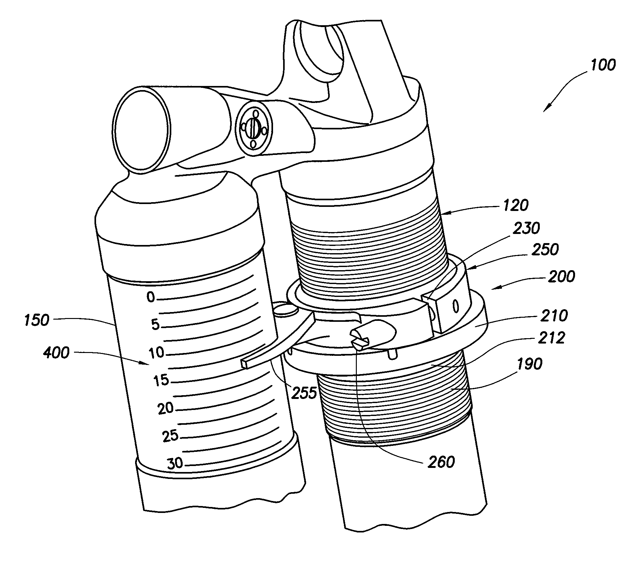
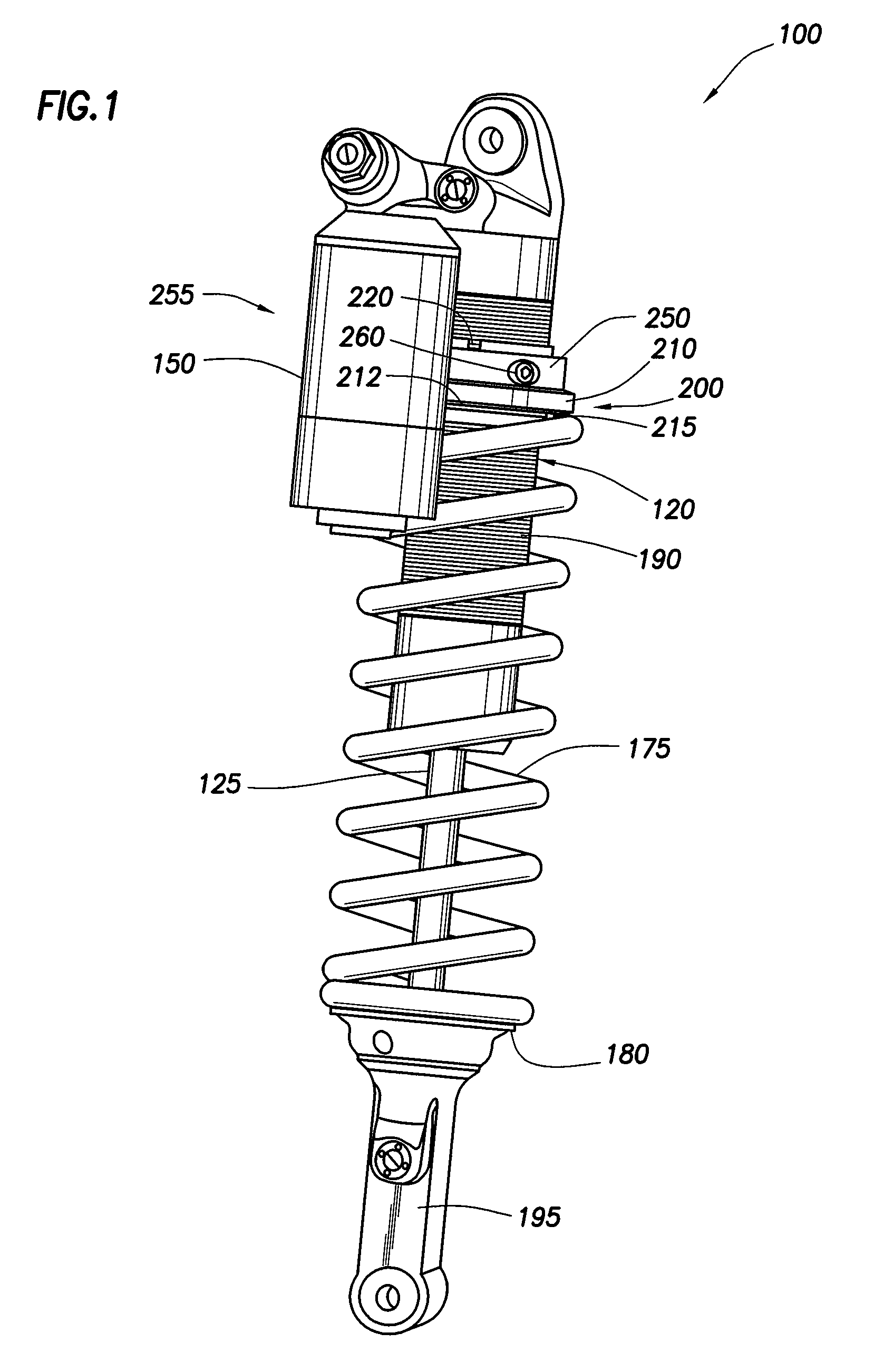
[0015]FIG. 1 shows an embodiment of a reservoir type shock absorber 100. The shock absorber includes a second component, such as in this embodiment a damper body 120, with a rod 125 extending therefrom and a reservoir 150 is in fluid (e.g. damping fluid such as hydraulic oil) communication with the damper body 120. The shock further includes a helical spring 175 annularly disposed about the damper body 120 and captured axially between a bottom clip 180 at a lower end and an adjuster assembly 200 at an upper end. An outer surface of the damper body 120 includes threads 190 that facilitate rotation of nut 210 and corresponding axial movement of the adjuster assembly 200 relative to the body 120.

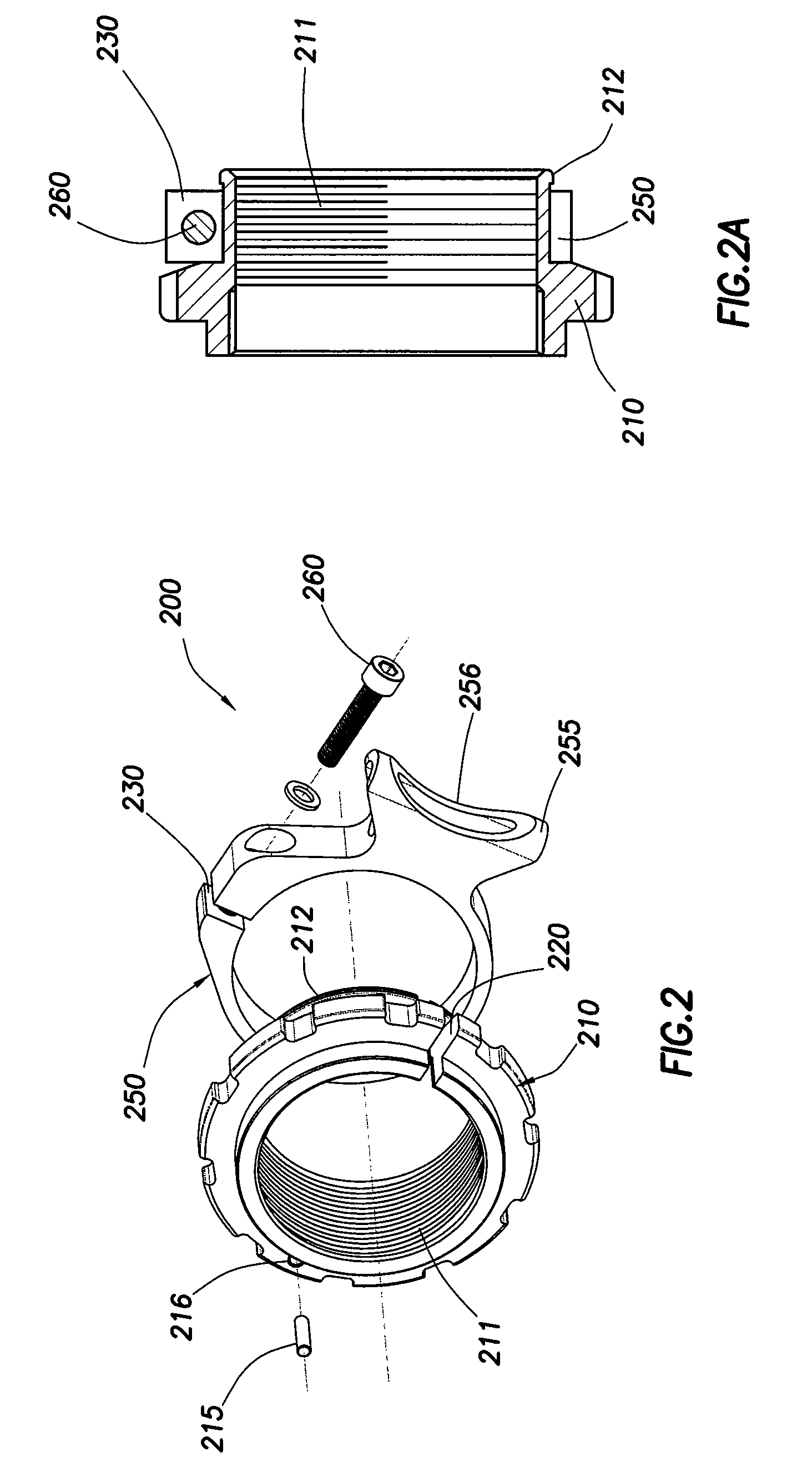
[0016]One embodiment of the adjuster assembly 200 is best appreciated with reference to all of the Figures and comprises a follower nut 210 and a clamp 250. In one embodiment the follower nut 210 includes a pin 215 for fitting into a hole 216 (shown in FIG. 2) in a flange of the nut 210. Referr...


PUM


Abstract

A method and apparatus for a suspension comprising a spring having a threaded member at a first end for providing axial movement to the spring as the spring is rotated and the threaded member moves relative to a second component. In one embodiment, the system includes a damper for metering fluid through a piston and a rotatable spring member coaxially disposed around the damper and rotatable relative to the damper.

Description

CROSS-REFERENCE TO RELATED APPLICATIONS[0001]This application claims benefit of U.S. provisional patent application Ser. No. 61 / 161,552, filed Mar. 19, 2009, and U.S. provisional patent application Ser. No. 61 / 161,620, filed Mar. 19, 2009. Each of the aforementioned related patent applications is herein incorporated by reference.BACKGROUND OF THE INVENTION[0002]1. Field of the Invention[0003]Embodiments of the present invention generally relate to a user-adjustable spring for use in a shock absorber.[0004]2. Description of the Related Art[0005]Integrated damper / spring vehicle shock absorbers often include a damper body surrounded by a mechanical spring. The damper often consists of a piston and shaft telescopically mounted in a fluid filled cylinder. The mechanical spring may be a helically wound spring that surrounds the damper body. Various integrated shock absorber configurations are described in U.S. Pat. Nos. 5,044,614; 5,803,443; 5,553,836; and 7,293,764; each of which is here...

Claims


Application Information

Patent Timeline
Patent Type & Authority Patents(United States)
IPC IPC(8): B60G15/00B60G15/06F16F1/12F16F9/56F16F9/32
CPCF16F1/121B60G15/063F16F9/3264F16F9/56B60G2204/1242B60G2204/61F16F2228/08B60G2500/30B60G2600/04B60G17/021B60G11/14
Inventor COX, CHRISTOPHER PAULMARQUEZ, MICHAEL DAVIDERICKSEN, EVERET OWEN
Owner FOX FACTORY
Learn More