Testing a circuit assembly that contains a piezoelectric switch

a piezoelectric switch and circuit assembly technology, applied in the direction of magnetic/electric field switches, instruments, measurement devices, etc., can solve the problems of parts that are subject to increased wear and tear

Active Publication Date: 2015-09-22
ESSEX ELECTRONICS
View PDF5 Cites 2 Cited by
  • Summary
  • Abstract
  • Description
  • Claims
  • Application Information

AI Technical Summary

Problems solved by technology

Known methods and apparatus for testing circuits frequently rely on mechanical parts that are subject to increased wear over time when compared to piezoelectric materials.

Method used


Image

  • Testing a circuit assembly that contains a piezoelectric switch
  • Testing a circuit assembly that contains a piezoelectric switch

Examples


Embodiment Construction

[0006]Those of ordinary skill in the art will realize that the following description of the present invention is illustrative only and not in any way limiting. Other embodiments of the invention will readily suggest themselves to such skilled persons.

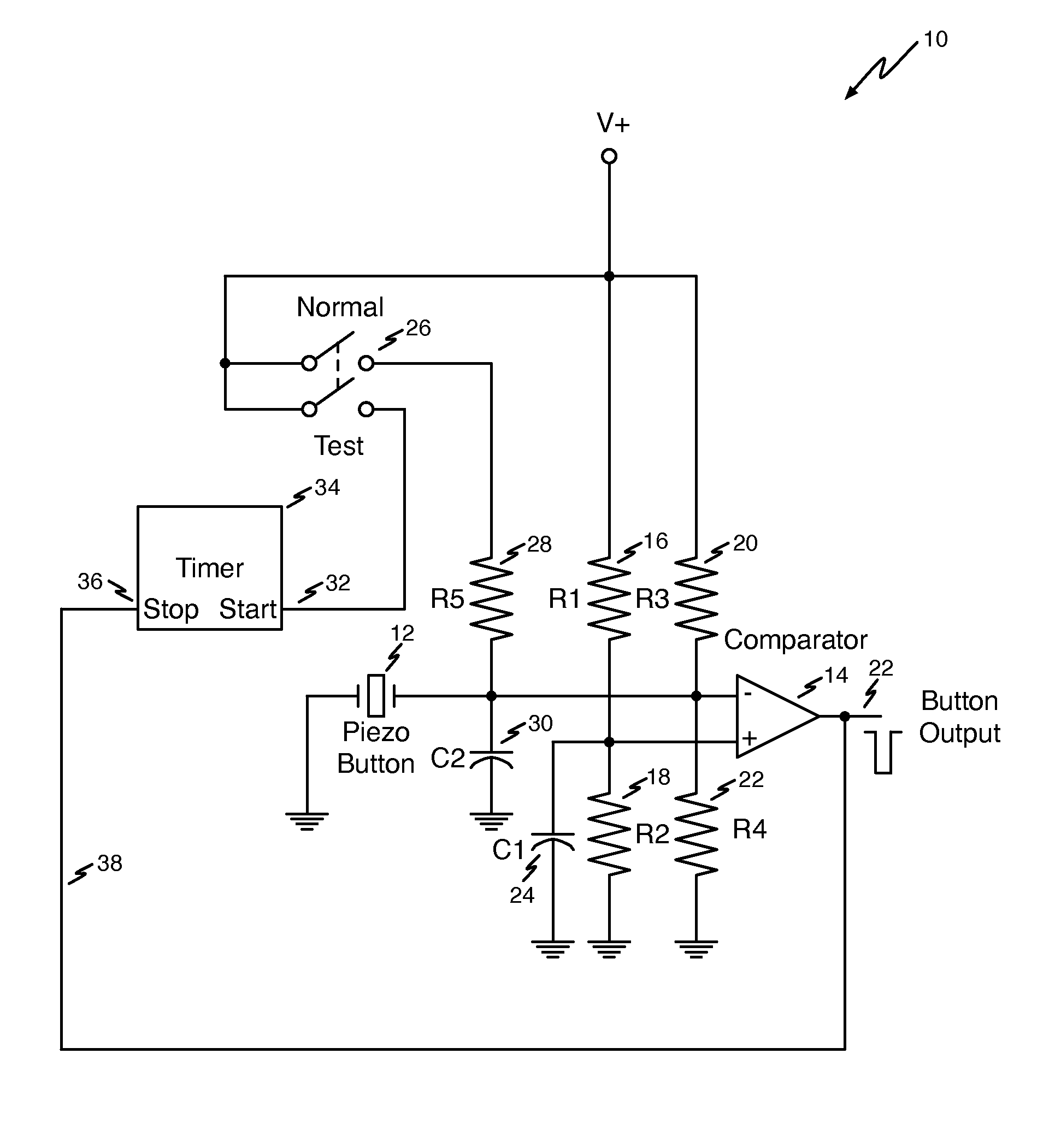
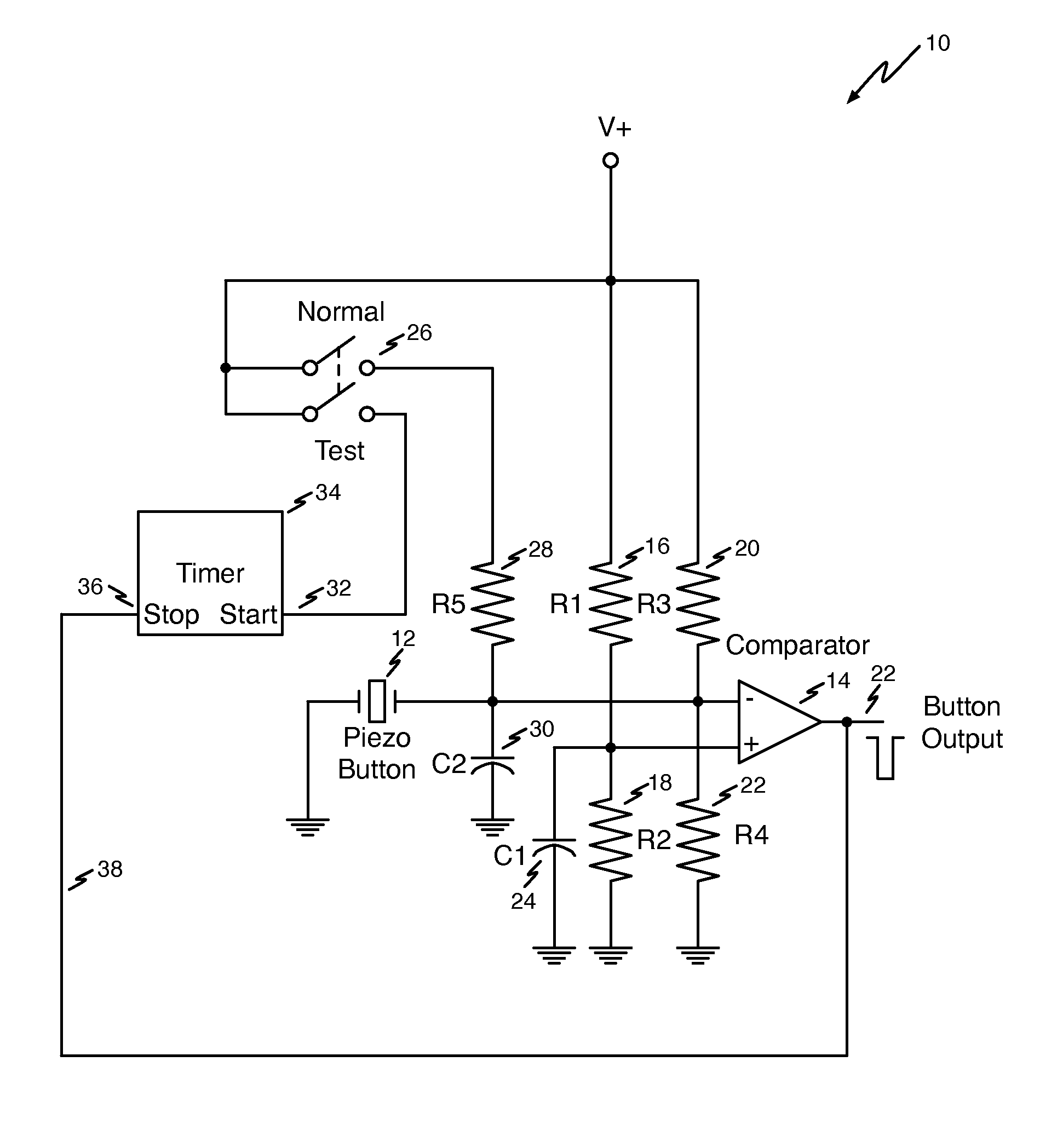
[0007]FIG. 1 shows an electrical diagram of an exemplary circuit that tests circuit assemblies that include a piezoelectric switch. The component values shown in the exemplary circuit of FIG. 1 are included for illustrative purposes. Persons of ordinary skill in the art will readily recognize that other component values may also be used. The optimal component values selected will depend on a number of design considerations commonly known by those in the electronics field. In one embodiment, a circuit 10 may include piezoelectric switch 12. In one embodiment, the piezoelectric switch 12 may be or include a piezoelectric crystal. The piezoelectric switch 12 may be connected between ground and the inverting input to a comparator 14. The no...


PUM


Abstract

A method of testing a circuit assembly that includes a piezoelectric switch may include driving a DC current into the piezoelectric switch. The method may further include measuring the time interval it takes to develop a predetermined voltage across the piezoelectric switch and comparing the measured time interval with a first predetermined time interval and a second predetermined time interval. The method may include identifying the circuit assembly as defective when the measured time interval is either less than the first predetermined time interval or more than the second predetermined time interval, and otherwise identifying the circuit assembly is operational.

Description

CROSS-REFERENCE TO RELATED APPLICATION[0001]This application claims the benefit of U.S. provisional patent application No. 61 / 616,057, filed on Mar. 27, 2012, the disclosure of which is incorporated by reference herein.BACKGROUND[0002]The present disclosure relates to electrical circuit assemblies. More particularly, the present disclosure relates to testing a circuit assembly that contains a piezoelectric switch. Piezoelectricity is the electric charge that builds up in certain solid materials and may be released in response to mechanical stress. Applying mechanical pressure to the piezoelectric material causes it output a voltage pulse that can be sensed by electronic circuits. Known methods and apparatus for testing circuits frequently rely on mechanical parts that are subject to increased wear over time when compared to piezoelectric materials. The electronics industry needs a more reliably way to test circuit assemblies.BRIEF DESCRIPTION[0003]In one embodiment, testing a circui...

Claims


Application Information

Patent Timeline
Patent Type & Authority Patents(United States)
IPC IPC(8): G01R31/327H01H11/00H01H36/00
CPCG01R31/3277G01R31/3278H01H11/0062H01H36/0006
Inventor HOGG, DOUGLASECHOLS, JOHN
Owner ESSEX ELECTRONICS
Why Eureka
Try Eureka