Hard disk drive assemblies with open side wall areas

a technology of hard disk drives and side walls, applied in the field of information handling systems, can solve the problems of airflow requirements that conflict with drive density desires in conventional dense enclosure systems, and achieve the effects of reducing air flow impedance, reducing cooling fan power costs, and increasing cooling efficiency

Active Publication Date: 2015-09-22
DELL PROD LP
View PDF15 Cites 4 Cited by
  • Summary
  • Abstract
  • Description
  • Claims
  • Application Information

AI Technical Summary

Benefits of technology

[0011]Disclosed herein are systems and methods that may be implemented to provide open areas in the opposing side walls of a hard disk drive assembly to optimize lateral (side-to-side) cooling air flow across a hard disk drive assembly in a storage enclosure or other type of hard drive enclosure (e.g., such as server chassis) by providing a flow channel defined within the base portion of the disk drive assembly to decrease impedance of lateral air flow across the disk drive assembly and through the hard drive enclosure.
[0012]In one exemplary embodiment, the side profile of a hard drive assembly may be configured with one or more open areas (e.g., with a series of holes or a series of notches defined in the side walls or rails of the drive assembly base portion) to allow air to pass side-to-side through a lateral flow channel provided by a cavity defined in the base portion of the drive assembly. In this way, the air may pass through the lateral flow channel and towards and contacting areas of the bottom surface of the drive assembly located between the sides of the hard drive assembly. Corresponding and complementary open areas in the form of air flow inlet / s and outlet / s may be also be defined in mating drive carrier assembly side components to allow passage of lateral side-to-side cooling air through the base portion flow channel of a mated drive assembly when the mated hard drive assembly and drive carrier assembly are installed together as a mountable hard drive system into a hard drive enclosure. In one embodiment, the provided lateral flow channel may be further implemented in a manner that results in substantially no loss to other functionalities of the drive assembly base portion, such as dynamic dampening, thermal dissipation, and HDI. The disclosed systems and methods may also be implemented in one embodiment in a manner that reduces air flow impedance across hard drive systems and through a storage enclosure (as compared to the air flow impedance across conventional hard drive systems similarly oriented and contained in a storage enclosure) in order to achieve both reduced cooling fan power costs and increased cooling efficiency for an individual drive assembly as well as to achieve increased cooling efficiency on a system level for multiple drive assemblies deployed in a dense storage enclosure.

Problems solved by technology

Thus, airflow requirements conflict with drive density desires in conventional dense enclosure systems.

Method used


Image

  • Hard disk drive assemblies with open side wall areas
  • Hard disk drive assemblies with open side wall areas
  • Hard disk drive assemblies with open side wall areas

Examples


Embodiment Construction

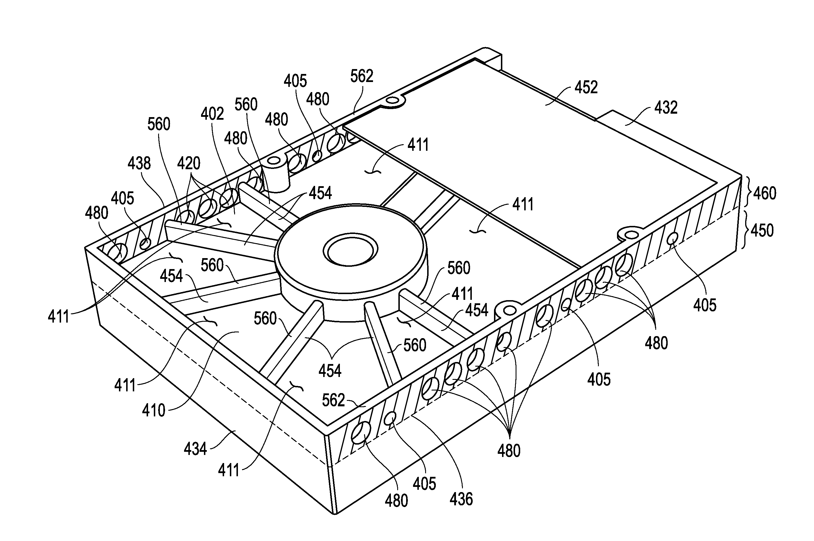
[0026]FIG. 4 illustrates one exemplary embodiment of a hard drive assembly 400 (e.g., such as a 3.5 inch HDD) having a cavity 410 that is defined in the bottom surface 402 of the base portion 460 of the casting (e.g., metal casting) of the hard drive assembly 400. Not shown is the opposing top surface of hard drive assembly 400 that may in one embodiment be a substantially flat and solid surface, e.g., with no cavity defined therein. As shown, drive assembly 400 has a front end 432, a back end 434, and two opposing side walls 436 and 438. Threaded mounting (fastener) holes 405 are defined in the opposing side walls 436 and 438 of drive assembly 400 to receive complementary mating threaded fasteners 506 for securably mounting a drive carrier assembly to hard drive assembly 400 as described further herein. In the exemplary embodiment of FIG. 4, a solid planar wall portion 411 of bottom surface 402 delineates and separates a hermetically sealed top section 450 from the cavity 410 of ba...


PUM


Abstract

The side profile of a hard drive assembly may be configured with one or more open areas to allow cooling air to pass side-to-side across the hard drive assembly through a lateral flow channel provided by a cavity defined in the base portion of the hard drive assembly.

Description

RELATED APPLICATIONS[0001]The present application is related in subject matter to concurrently filed patent application Ser. No. 14 / 023,939, entitled “DISK DRIVE CARRIERS AND MOUNTABLE HARD DRIVE SYSTEMS WITH IMPROVED AIR FLOW” by Mundt et al., which is incorporated herein by reference in its entirety.FIELD OF THE INVENTION[0002]This invention relates generally to information handling systems and, more particularly, to hard disk drive assemblies for information handling systems.BACKGROUND OF THE INVENTION[0003]As the value and use of information continues to increase, individuals and businesses seek additional ways to process and store information. One option available to users is information handling systems. An information handling system generally processes, compiles, stores, and / or communicates information or data for business, personal, or other purposes thereby allowing users to take advantage of the value of the information. Because technology and information handling needs a...

Claims


Application Information

Patent Timeline
Patent Type & Authority Patents(United States)
IPC IPC(8): G06F1/16G06F1/18
CPCG06F1/187G11B33/128G11B33/142
Inventor MUNDT, KEVIN W.KWON, HAESUNGYU, FRANK W.
Owner DELL PROD LP
Why Eureka
Try Eureka