Compact tapered slot antenna

a technology of tapered slot antenna and compact structure, which is applied in the direction of slot antenna, waveguide type device, electrical apparatus, etc., can solve the problems of affecting the efficiency of the antenna, affecting the use of the antenna, and the cost of previously used low temperature co-fired ceramic construction, etc., and achieves the effect of wide frequency bandwidth, less surface area, and convenient portability and electronic devi

Inactive Publication Date: 2015-09-22
TECHNION RES & DEV FOUND LTD
View PDF16 Cites 25 Cited by
  • Summary
  • Abstract
  • Description
  • Claims
  • Application Information

AI Technical Summary

Benefits of technology

[0009]The present disclosure describes a new exemplary compact broadband end-fire Tapered Slot Antenna. Unlike prior art TSAs which use a generally orthogonal microstrip-to-slot transition between the microstrip feed line and the tapered slot, the antenna of the present disclosure features collinear stubs. This new transition provides a relatively wide frequency bandwidth. This transition also occupies less surface area than prior art transitions, making it more suitable for portable electronic devices. In addition, the antenna may advantageously be supported on a metallic fork-shaped carrier, which gives the antenna good rigidity, and may also incorporate a metallic reflector, which increases the antenna's directive gain. Such a reflector may also serve to reduce the possible effects of other components or elements of the RF module on the antenna. The antenna may be manufactured by printing on a suitable dielectric substrate, especially a thin liquid crystal polymer (LCP) substrate, with the advantages which such substrates provide. The performance of different examples of tapered slot antennas constructed as described in this application, can be simulated by use of an RF 3D EM field simulation and circuit design program. The TSA can be used for any frequency band, including the band from 56 GHz up to 66 GHz., incorporating the partial operating bands for WPAN application, namely 57-64, 59-62, 62-63, and 65-66 GHz. allocated in various countries for high-speed data rate wireless communications.

Problems solved by technology

This form of MST has an inherent narrow bandwidth characteristic, such that the use of the antenna may be limited.
In these antennas, the choice of the substrate material may greatly affect the antenna efficiency.
Previously used low temperature co-fired ceramic construction is costly, both from the substrate cost aspect, and from the fabrication costs because of the multilayer process.
In the 60 GHz band, it is substantially more difficult to achieve wide bandwidths.

Method used


Image

  • Compact tapered slot antenna
  • Compact tapered slot antenna
  • Compact tapered slot antenna

Examples


example

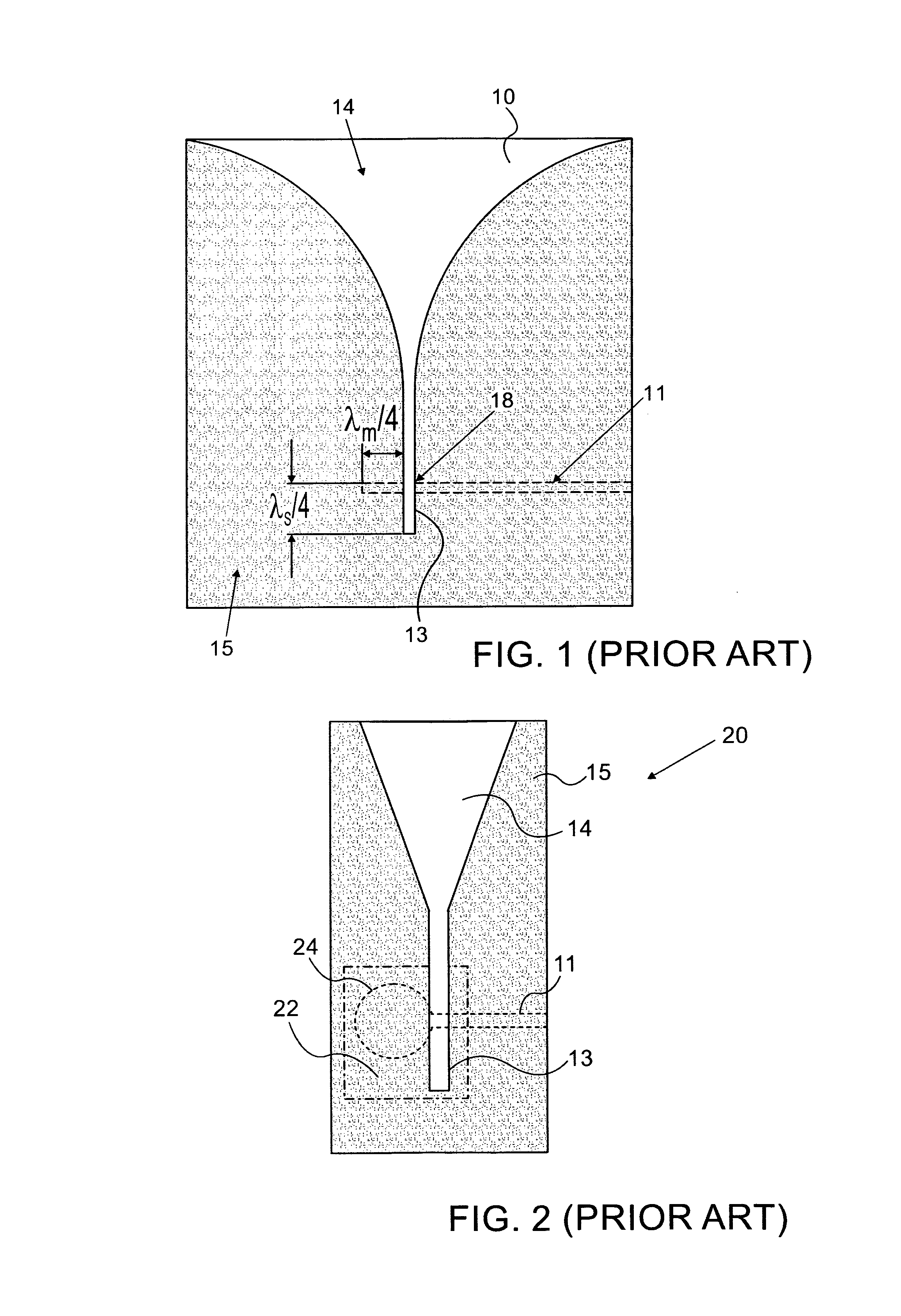
[0047]Design of an exemplary antenna was carried out in three stages by use of the CST Microwave Studio Suite, available from CST AG, of Darmstadt, Germany. In the first stage, the antenna was considered without the carrier and reflector. The initial topology and dimensions of the slot chosen were similar to those of the compact linear-tapered slot antenna (LTSA) described in “Linear tapered cavity-backed slot antenna for millimeter-wave LTCC modules” by I. K. Kim et al, published in IEEE Antennas Wireless Propag. Lett., Vol. 5, pp. 175-178, 2006. Specifically, a feeding slot of width s=0.2 mm was used, and a linearly tapered slot of length lt=4 mm and aperture of width w=2.5 mm.

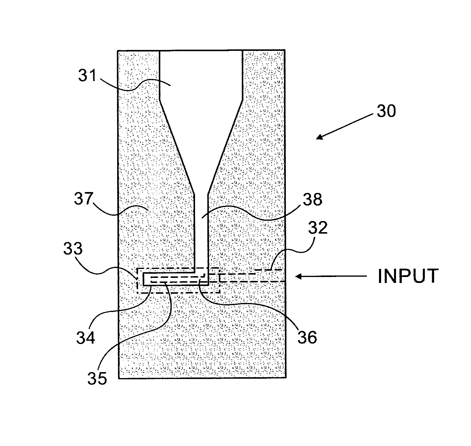
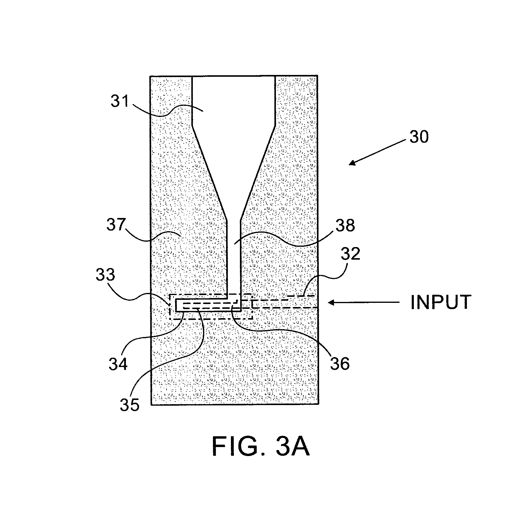
[0048]Unlike the prior art designs, with their simple cross-over transition region, the novel microstrip-to-slot transition topology described in this disclosure, was used, with the microstrip and slot stubs laid collinearly, partially overlapping each other, as shown in FIGS. 3A and 4A-4B. The dimensions of...


PUM


Abstract

A compact endfire tapered slot antenna, which may be advantageously printed on a low permittivity Liquid Crystal Polymer substrate. The antenna features a microstrip-to-slot transition, in which the matching stubs of the slotline antenna feed and the microstrip input line are collinear. This is achieved using a 90° bend in the slotline. The antenna is consequently of smaller size, and has improved bandwidth over prior art geometries. The antenna may be carried on a fork-shaped metallic carrier, which gives it good rigidity, and may incorporate a metallic reflector, which increases its directive gain. The antenna is simpler to manufacture and a less costly alternative to conventional 60-GHz tapered slot antennas printed on multilayer LTCC substrates. It can be used both as an individual radiator as well as an element of an antenna array and is readily integrated with an RF module for use in future WPAN applications.

Description

CROSS-REFERENCE TO RELATED APPLICATIONS[0001]This application is a U.S. National Phase Application under 35 U.S.C. 371 of PCT International Application No. PCT / IL2011 / 000120, which has an international filing date of Feb. 2, 2011, and which claims the benefit of priority of U.S. Provisional Patent Application No. 61 / 300,457, filed Feb. 2, 2010, which is incorporated herein by reference.FIELD OF THE INVENTION[0002]The present invention relates to the field of tapered slot RF and microwave antennas, especially for use in broadband millimeter wave applications.BACKGROUND OF THE INVENTION[0003]The development of new wireless communication systems in the microwave and millimeter-wave bands have spurred the design of new types of compact, wideband, efficient, and low-cost antennas and antenna arrays. Among these, antennas manufactured by printed circuit technology have been increasingly widely used, because they are compact and low-cost. The tapered slot antenna (hereinafter TSA) is one s...

Claims


Application Information

Patent Timeline
Patent Type & Authority Patents(United States)
IPC IPC(8): H01Q13/10H01P5/02
CPCH01Q13/106H01P5/028H01Q13/085
Inventor PAZIN, LEVLEVIATAN, YEHUDA
Owner TECHNION RES & DEV FOUND LTD
Why Eureka
Try Eureka