
Modular mobile crane

Active Publication Date: 2015-10-06
LIEBHERR WERK EHINGEN
View PDF20 Cites 3 Cited by
  • Summary
  • Abstract
  • Description
  • Claims
  • Application Information

AI Technical Summary

Benefits of technology

The present invention provides a modular mobile crane that can be moved quickly and at the lowest possible cost of installation or deinstallation on a construction site. The crane is able to accomplish the displacement from one site of use to another site of use as autonomously as possible. The under carriage of the crane can be connected via the at least one connection point, alternatively via at least one support-side connection point, to the support, and to the upper carriage connected to the support, or via at least one jib-side connection point to the jib separated from the upper carriage. This design of the crane allows large component groups to be transported from one site of use to another site of use without requiring disassembly thereof, resulting in a significant reduction in transport cost on the construction site. The under carriage also comprises a complete vehicle with several drive axles and at least one drive unit, which increases the usable transport surface area for the parts of the crane that are to be transported. The crane can be moved on the construction site in a very simple manner from one site of use to another site of use, largely without first having to be disassembled or reassembled. The under carriage can also be displaced separately on the support on the construction site, and perform other tasks.

Problems solved by technology

Working with large lifting heights and heavy loads requires very large cranes.
The transport of a large crane up to a construction site and on the construction site is relatively expensive.
It is known that such large cranes are also very heavy, and they are frequently broken up into assembly groups for their move to the construction site.
However, the loads that the vehicle can carry are limited here as well.
If the crane is very large, in comparison to the carriage, it is technically no longer possible to move the crane in a completely equipped state.
However, the modules then have to be assembled on site, which entails considerable costs and expenditure of time.

Method used


Image

  • Modular mobile crane
  • Modular mobile crane
  • Modular mobile crane

Examples


Embodiment Construction

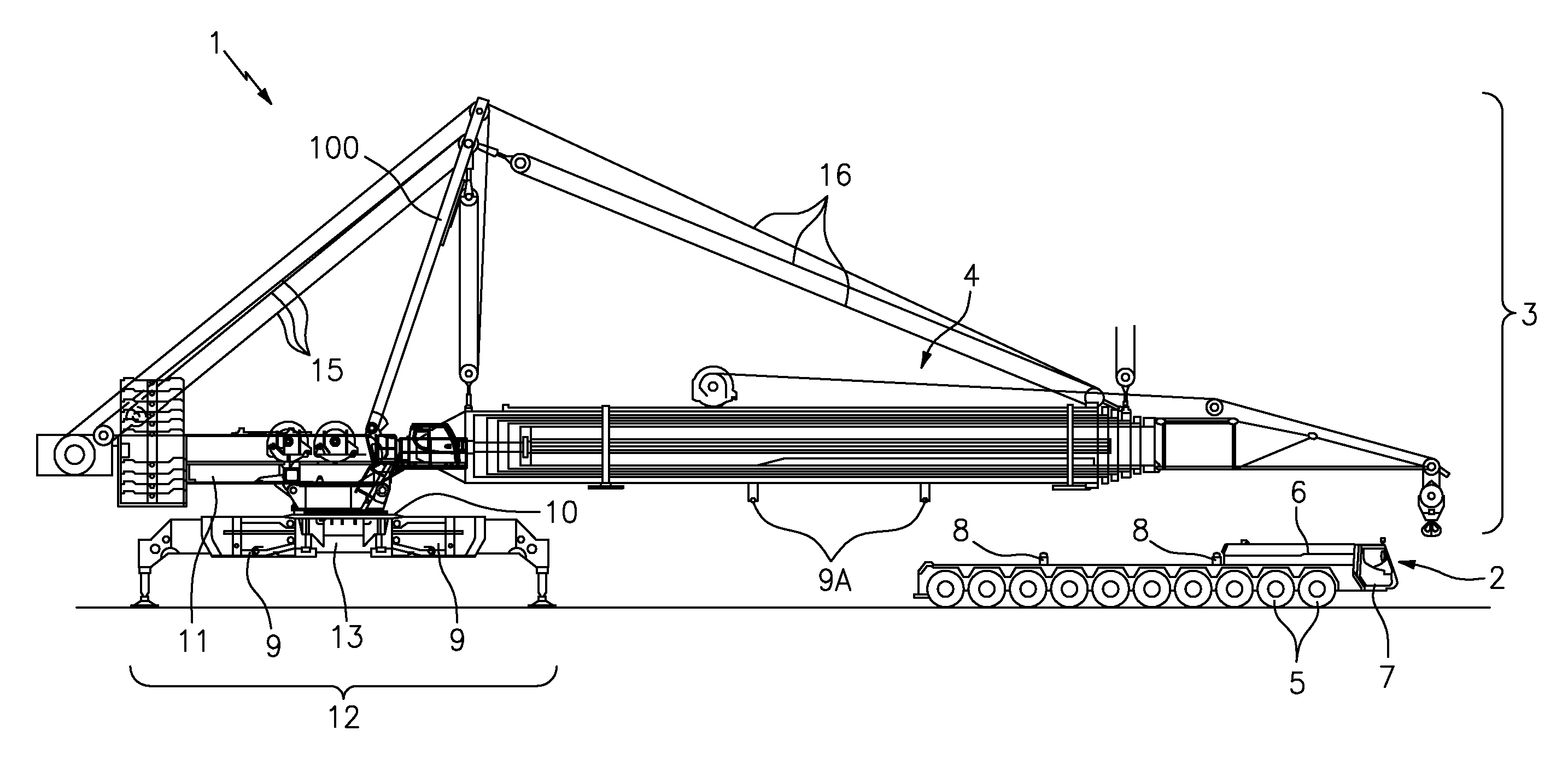
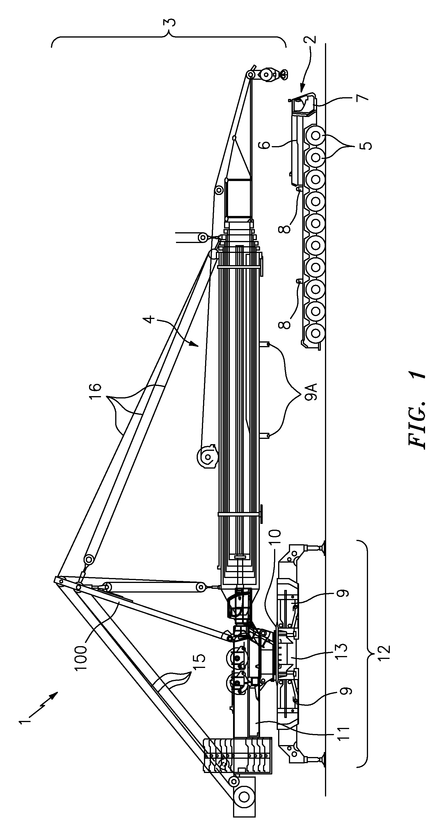
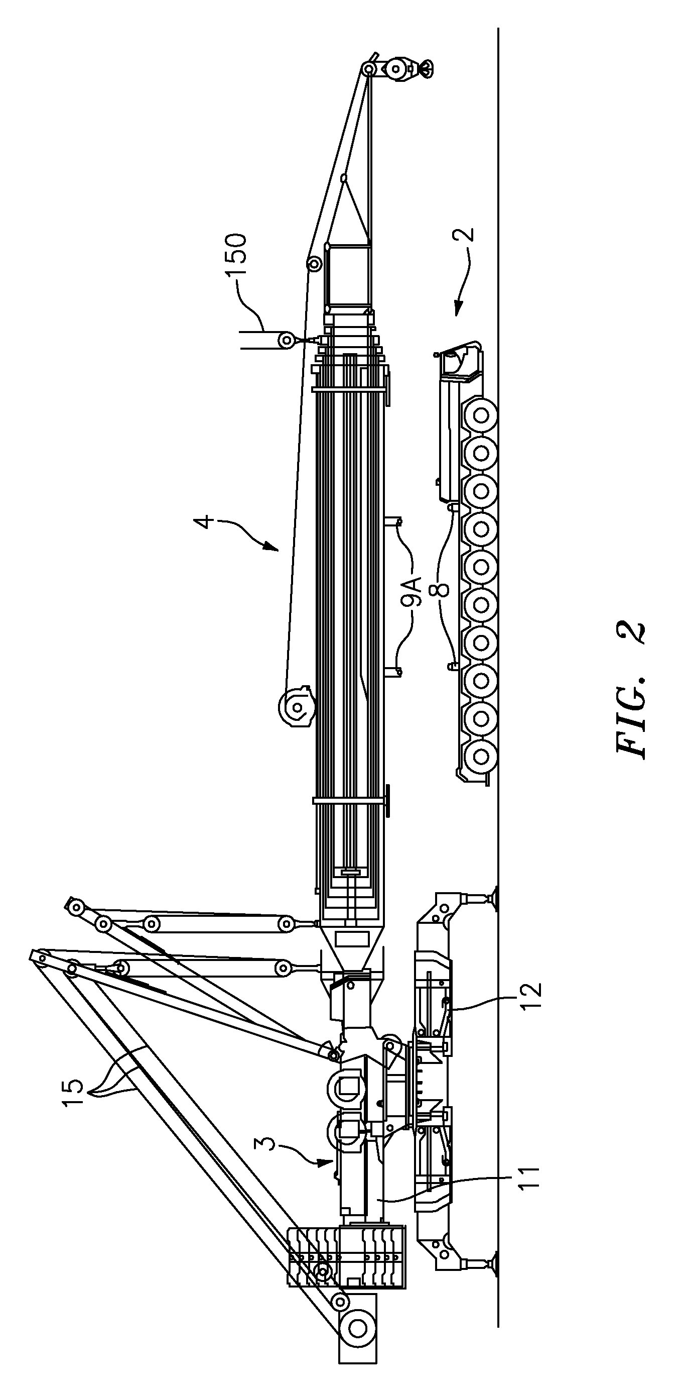
[0040]FIG. 1 shows a modular mobile crane 1 which consists of an under carriage 2, a support 12, an upper carriage 3, and a jib 4 connected to the upper carriage. The lower carriage 2 is designed as a complete vehicle and it comprises several drive axles 5, as well as a drive unit 6. The under carriage 2 furthermore comprises a driver cabin 7 which, as can be seen in FIG. 1, is in a relatively low position, so that, for example, a jib deposited on the under carriage 2 can project over the driver cabin 7 (see FIG. 3).

[0041]In FIG. 1, the under carriage 2 is represented in a state separated from the support 12 and from the upper carriage 3 arranged rotatably on said under carriage. The support 12 and the upper carriage 3 together form an operational crane which is fully operational at a first site of use.

[0042]The construction of the upper carriage in itself is known. Below, only the parts required for the description of the present invention are indicated. The upper carriage 3 consis...


PUM


Abstract

The present disclosure relates to a crane, in particular to a modular mobile crane, with an under carriage, a support, and an upper carriage which comprises an upper carriage frame and a jib which can be separated from the upper carriage, wherein the under carriage comprises at least one connection point. According to the invention, the under carriage can be connected via the at least one connection point alternatively via at least one support-side connection point to the support, and to the upper carriage connected to said support, or via at least one jib-side connection point to the jib separated from the upper carriage.

Description

BACKGROUND OF THE INVENTION[0001]The present invention relates to a crane, in particular to a modular mobile crane, as well as to a method for moving and displacing such a crane.[0002]Working with large lifting heights and heavy loads requires very large cranes. Such cranes are used on large construction sites at different sites of use. The transport of a large crane up to a construction site and on the construction site is relatively expensive. Thus, it is advantageous if the crane can be moved autonomously, and if no other transport vehicles have to to be reserved at the construction site or need be transported to the construction site.[0003]It is known that such large cranes are also very heavy, and they are frequently broken up into assembly groups for their move to the construction site. The justification for this relates to the admissible weights and to the maximum admissible or economically transportable dimensions. However, it must be kept in mind that, during the transport ...

Claims


Application Information

Patent Timeline
IPC IPC(8): B66C23/72B66C23/62B66C23/36
CPCB66C23/62B66C23/365
Inventor WILLIM, HANS-DIETER
Owner LIEBHERR WERK EHINGEN
Learn More