Information processing apparatus, function setup method, and computer program
a technology of information processing apparatus and function, applied in the field of user interface technique, can solve the problems of difficult to easily and efficiently perform the setup desired by the photographer, and achieve the effect of convenient and efficient setup
- Summary
- Abstract
- Description
- Claims
- Application Information
AI Technical Summary
Benefits of technology
Problems solved by technology
Method used
Image
Examples
embodiment 1
[0042
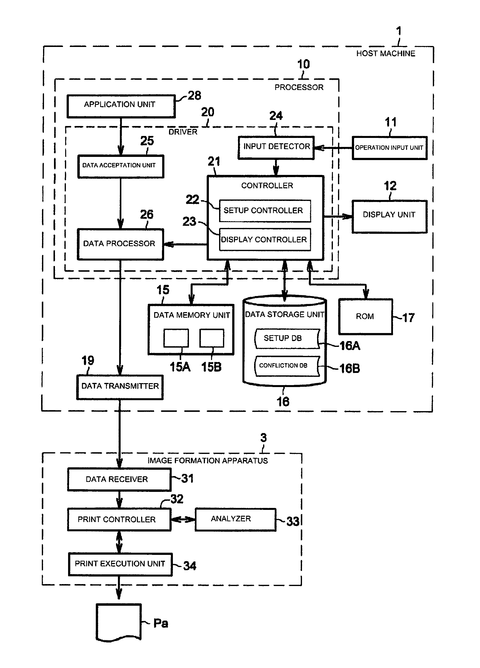
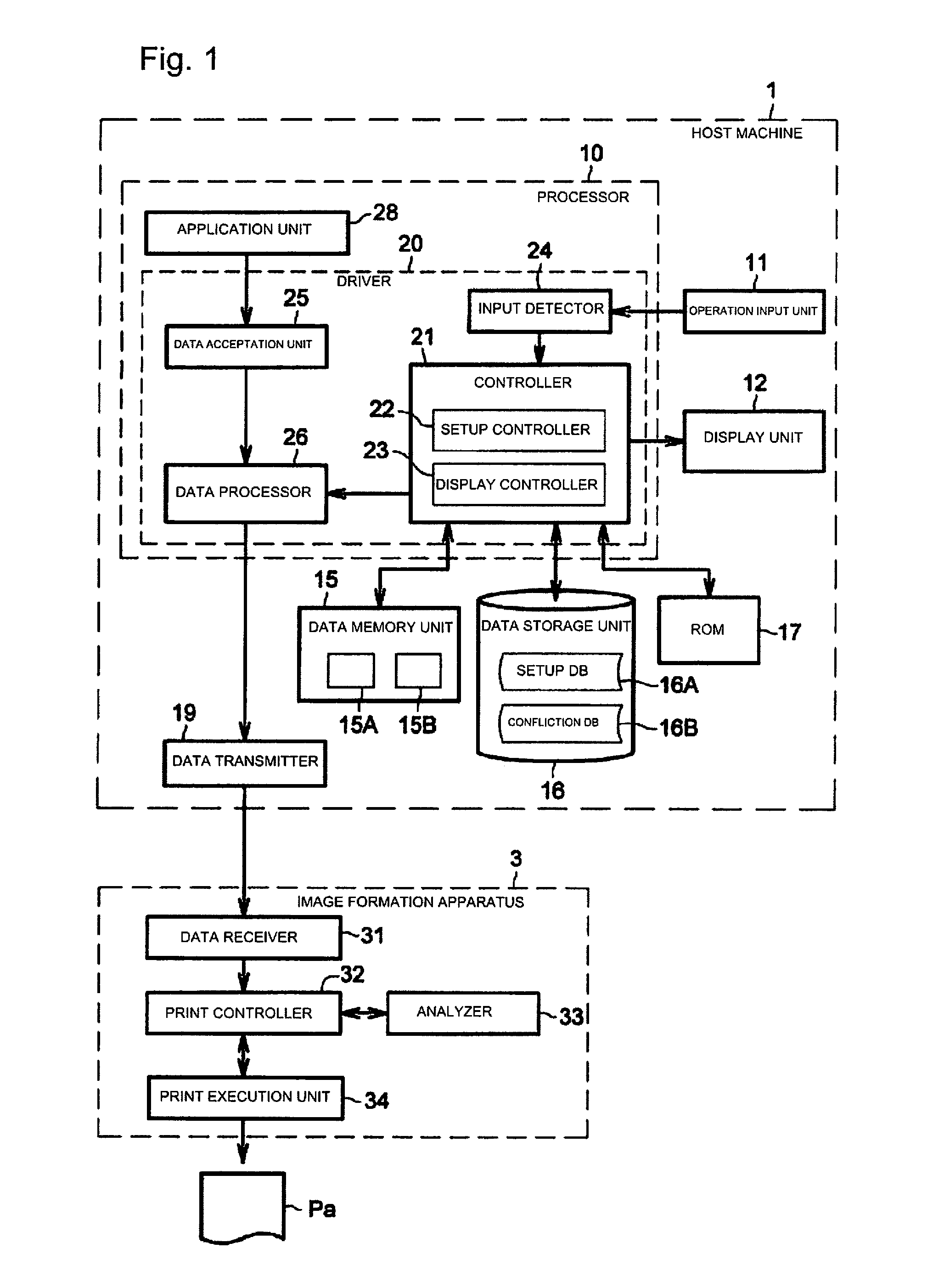
[0043]FIG. 1 is a block diagram illustrating a schematic configuration of a print system including: host machine 1 which is an information processing apparatus in Embodiment 1 of the invention; and image formation apparatus 3.
[0044]As illustrated in FIG. 1, host machine 1 includes: processor 10 configured to execute a function setup process for setting various setup items related to operation conditions of functions of image formation apparatus 3; operation input unit 11 configured to receive an operation input made by an user; display unit 12 configured to display a setup screen; data memory unit 15 configured to store data generated by processor 10; data storage unit 16 configured to store databases referred to in the function setup process; ROM (Read Only Memory) 17 configured to store a computer program implementing the function setup process; and data transmitter 19 configured to transmit an output of processor 10 to external image formation apparatus 3.
[0045]Processor 10 ...
embodiment 2
[0134
[0135]Next, Embodiment 2 of the invention is described. FIG. 19 is a block diagram illustrating a schematic configuration of a print system including: host machine 2 which is an information processing apparatus in Embodiment 2 of the invention; and image formation apparatus 3. The configuration and operations of image formation apparatus 3 illustrated in FIG. 19 are the same as the configuration and operations of image formation apparatus 3 illustrated in FIG. 1.
[0136]The configuration of host machine 2 in the embodiment is the same as the configuration of host machine 1 in Embodiment 1 described above, except for processor 10B. Moreover, the configuration of processor 10B is the same as the configuration of processor 10 in Embodiment 1 described above, except for the point that processor 10B includes driver 20B instead of driver 20 illustrated in FIG. 1. Furthermore, the configuration of driver 20B in the embodiment is the same as the configuration of driver 20 in Embodiment 1...
embodiment 3
[0146
[0147]Next, Embodiment 3 of the invention is described. FIG. 25 is a block diagram illustrating a schematic configuration of a print system including: host machine 1M which is an information processing apparatus in Embodiment 3 of the invention; and image formation apparatus 3. The configuration and operations of image formation apparatus 3 illustrated in FIG. 25 are the same as the configuration and operations of image formation apparatus 3 illustrated in FIG. 1.
[0148]The configuration of host machine 1M in the embodiment is the same as the configuration of host machine 1 in Embodiment 1 described above, except for processor 10M. Moreover, the configuration of processor 10M is the same as the configuration of processor 10 in Embodiment 1 described above, except for the point that processor 10M includes driver 20M instead of driver 20 illustrated in FIG. 1. Furthermore, the configuration of driver 20M in the embodiment is the same as the configuration of driver 20 in Embodiment...
PUM
 Abstract
Description
Claims
Application Information
 - R&D
- Intellectual Property
- Life Sciences
- Materials
- Tech Scout
- Unparalleled Data Quality
- Higher Quality Content
- 60% Fewer Hallucinations
Browse by: Latest US Patents, China's latest patents, Technical Efficacy Thesaurus, Application Domain, Technology Topic, Popular Technical Reports.
© 2025 PatSnap. All rights reserved.Legal|Privacy policy|Modern Slavery Act Transparency Statement|Sitemap|About US| Contact US: help@patsnap.com


