Double-capped short arc flash lamp

a short arc flash lamp and double-capped technology, applied in the direction of gas discharge lamp details, electric discharge lamps, electrical apparatus, etc., can solve the problems of optical system light output drop, achieve accurate relative positional relationship, simplify the structure of flash lamps, facilitate and simplify sealing work

Inactive Publication Date: 2015-10-06
USHIO DENKI KK
View PDF2 Cites 2 Cited by
  • Summary
  • Abstract
  • Description
  • Claims
  • Application Information

AI Technical Summary

Benefits of technology

[0018]An object of the present invention is to provide a double-capped short arc flash lamp that can eliminate the positional deviation (offset, undesired movement) of the inner and outer leads of the auxiliary electrodes when the second sealing tube is fused and sealedly joined to the sealing glass tube. The inner and outer leads of the auxiliary electrodes are placed between the second sealing tube and the sealing glass tube. When the inner and outer leads of the auxiliary electrodes have no positional deviation, accurate positional relationship is established between the two auxiliary electrodes because the auxiliary electrodes are provided at the ends of the inner leads.
[0019]Another object of the present invention is to provide a double-capped short arc flash lamp that can avoid breakage of the welded portions between the inner and outer leads and the metallic foils.
[0020]Still another object of the present invention is to provide a double-capped short arc flash lamp that does not need a component (supporter) for fixing the positions of the inner leads, and that has the sealing tube with a smaller outer diameter so as to reduce the light shielding region.
[0021]Yet another object of the present invention is to provide a double-capped short arc flash lamp that can facilitate and simplify the sealing work.
[0026]In the overlapping area between the second sealing tube and the sealing glass tube of the flash lamp, the lead receiving grooves are formed in the outer surface (outer circumference) of the sealing glass tube, and the lead receiving grooves extend in the axial direction of the sealing glass tube. Because the inner leads and outer leads of the auxiliary electrodes are received in the grooves, the inner and outer leads do not deviate (move, shift) from the desired positions when the second sealing tube is fused and sealed to the sealing glass tube. This facilitates and simplifies the sealing work. Also, accurate relative positional relationship is obtained between the two auxiliary electrodes.
[0027]Therefore, a separate component for fixing the positions of the auxiliary electrodes is not needed. This simplifies the structure of the flash lamp. Further, the second sealing tube can have a smaller outer diameter. This reduces the light shielding area. In addition, no breakage occurs in the welding joint between the metallic foils and the inner leads and between the metallic foils and the outer leads.

Problems solved by technology

As a result, the light output from the optical system drops.

Method used


Image

  • Double-capped short arc flash lamp
  • Double-capped short arc flash lamp
  • Double-capped short arc flash lamp

Examples


first embodiment

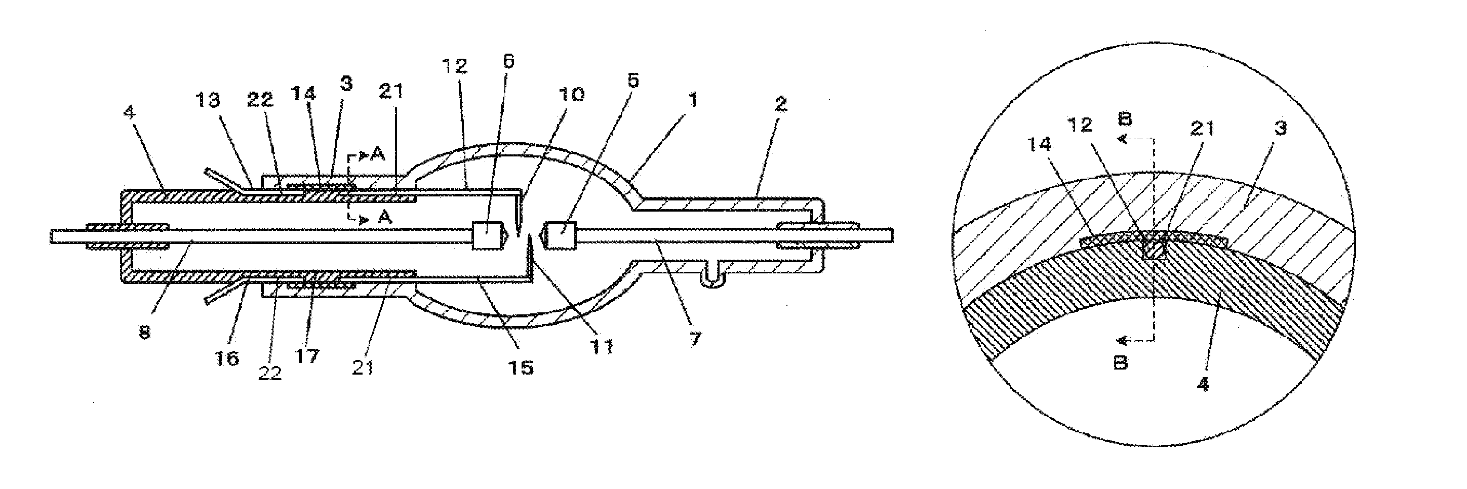
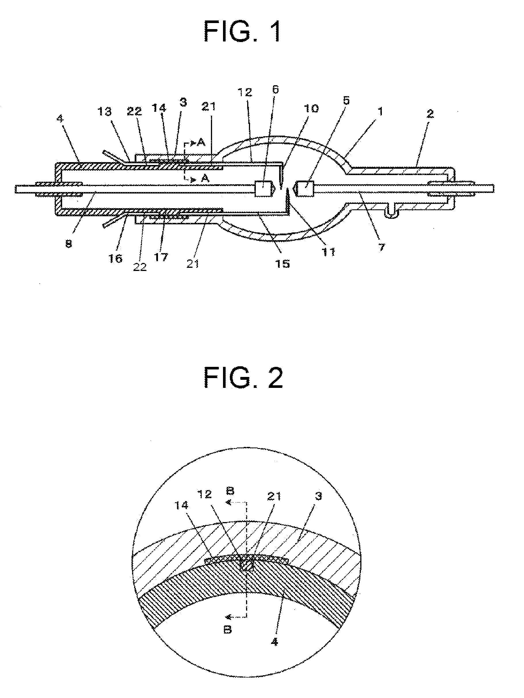
[0037]A first embodiment of the present invention will be described with reference to FIG. 1 that illustrates an overall cross-sectional view of a double-capped short arc flash lamp, FIG. 2 that illustrates a cross-sectional view taken along the line A-A in FIG. 1, and FIG. 3 that illustrates a cross-sectional view taken along the line B-B in FIG. 2. Like reference numerals are used to designate like components of the double-capped short arc flash lamp in FIGS. 1-3 and FIGS. 6-7.

[0038]As schematically shown in FIG. 1 and precisely shown in FIGS. 2 and 3, the double-capped short arc flash lamp has a pair of main electrodes 5 and 6, a pair of auxiliary electrodes 10 and 11 for starting (triggering discharge), a first sealing tube 2, a second sealing tube 3, and a sealing glass tube 4. In an overlapping area between the second sealing tube 3 and the sealing glass tube 4, there are formed lead receiving grooves 21 and 22 in the outer surface (outer circumference) of the sealing glass tu...

second embodiment

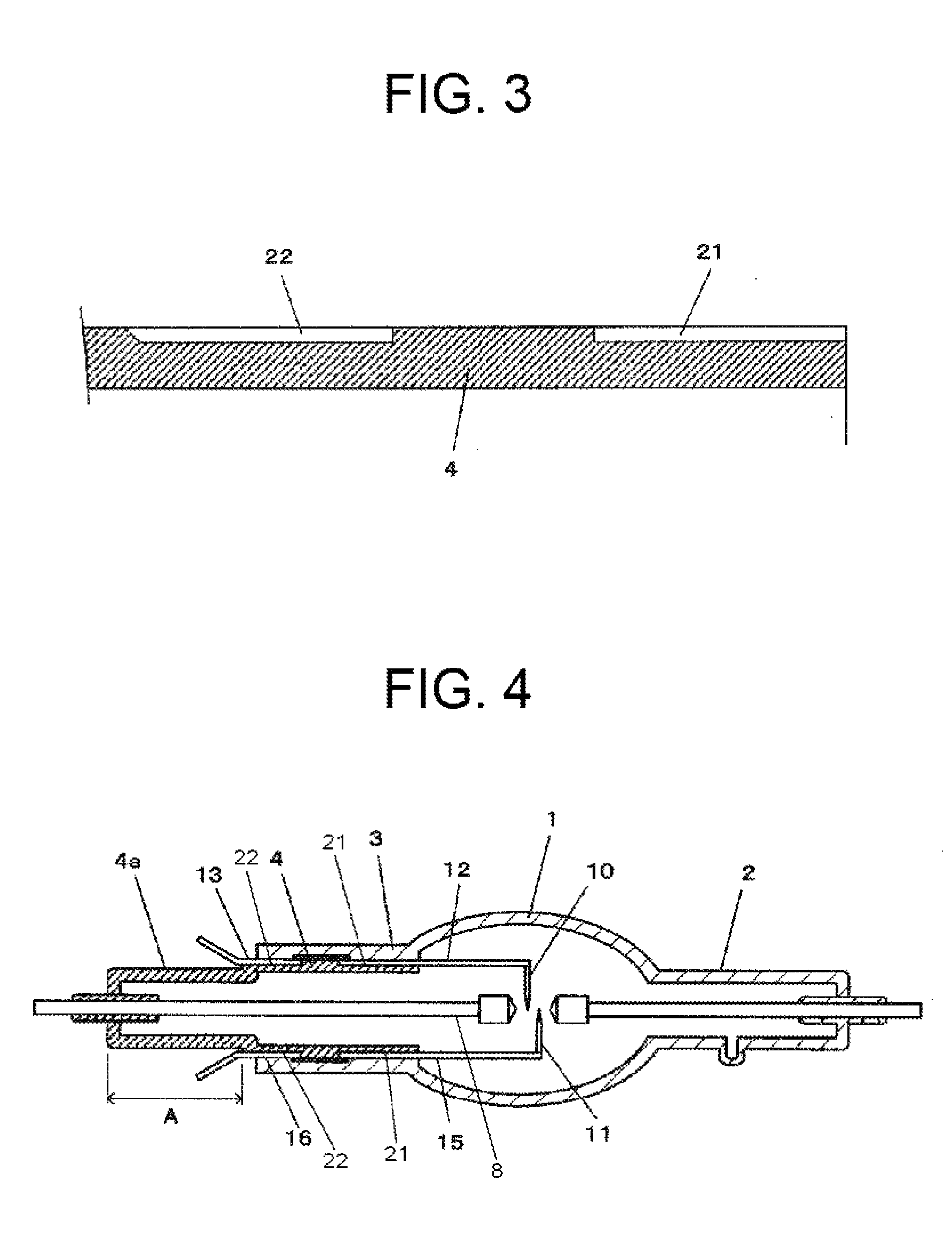
[0050]Referring to FIG. 4, a second embodiment of the present invention will be described. Like reference numerals are used to designate like components in the first and second embodiments. The second embodiment is different from the first embodiment of FIG. 1 in that the sealing glass tube 4 has a reduced diameter portion 4a that extends rearward (to the left in FIG. 4) from the second sealing tube 3 (extends outside the second sealing tube 3) in the region A. In other words, the rear portion (outside portion) 4a of the sealing glass 4 has a smaller diameter than that portion of the sealing glass 4 which overlaps the second sealing tube 3.

[0051]Because the sealing glass tube 4 has the rear portion 4a having a reduced diameter that defines a step portion, rearward (backward, outward) movements of the outer leads 13 and 16 received in the grooves 22 become easier.

third embodiment

[0052]Referring to FIG. 5, a third embodiment of the present invention will be described. The third embodiment is a modification to the second embodiment. Like reference numerals are used to designate like components in the second and third embodiments. The third embodiment is different from the second embodiment in that the rear portion 4a of the sealing glass tube 4 has a further reduced diameter, as compared with the configuration shown in FIG. 4. The rear portion 4a having the further reduced diameter further facilitates the rearward movements of the outer leads 13 and 16 received in the grooves 22. In this configuration, the sealing between the rear end of the sealing glass tube 4 and the electrode core wire 8 is made by a graded seal (not shown), and the rear end of the sealing glass tube 4 has a larger diameter than the reduced diameter portion 4a due to the design of the graded seal and / or the work associated with the graded seal.

[0053]As described above, the double-capped s...


PUM


Abstract

A double-capped short arc flash lamp includes an arc tube, a pair of main electrodes disposed in the arc tube, and a pair of auxiliary electrodes disposed in the arc tube. The flash lamp also includes inner leads and outer leads associated with the two auxiliary electrodes, respectively. The flash lamp also includes a first sealing tube and a second sealing tube provided at opposite ends of the arc tube. A sealing glass tube is partly received in the second sealing tube. Grooves are formed in the outer surface of the sealing glass tube in a region where the sealing glass tube overlaps the second sealing tube. The grooves extend in the axial direction of the sealing glass tube, and are configured to receive the inner leads and the outer leads. Metallic foils electrically connect the inner leads with the outer leads, respectively.

Description

FIELD OF THE INVENTION[0001]The present invention relates to a double-capped short arc flash lamp, and more particularly to a double-capped short arc flash lamp that has a double tube structure at one of sealing tube portions.DESCRIPTION OF THE RELATED ART[0002]Discharge lamps for flashing (flash lighting) are widely used in industry applications such as flash annealing in a semiconductor manufacturing process or the like. The present invention pertains to a lamp that is particularly suitable to, for example, an exposing process with vacuum ultraviolet light.[0003]The exposing process with the vacuum ultraviolet light requires use of light that can irradiate a small area with high density light in a short time and has relatively small irregularities (unevenness) in the light directivity and distribution, i.e., use of light that is close to parallel light.[0004]One typical example of conventional lamps which are used in the above-mentioned exposing process is a flash lamp having a va...

Claims


Application Information

Patent Timeline
Patent Type & Authority Patents(United States)
IPC IPC(8): H01J17/30H01J61/54H01J61/36
CPCH01J61/545H01J61/361H01J61/36H01J61/80H01J61/366H01J61/86H01J61/90
Inventor KASE, MASAHIKOHIRAISHI, TAKAYUKIISHIKAWA, HIROHISA
Owner USHIO DENKI KK
Why Eureka
Try Eureka