
Window support and method for room air conditioner installation

a technology for air conditioners and brackets, which is applied in the direction of building scaffolds, lighting and heating apparatus, heating types, etc., can solve the problems of not always perfectly sized for the window opening, the unit is not always securely mounted in the window, and the weight of the window unit is very heavy, so as to reduce the pressure on the window frame

Active Publication Date: 2015-10-20
TOPSHELF A C
View PDF75 Cites 37 Cited by
  • Summary
  • Abstract
  • Description
  • Claims
  • Application Information

AI Technical Summary

Benefits of technology

The present invention is a bracket designed to safely and securely support air conditioning units in window frames. It allows for adjustability of window sizes, without the need for drilling, tools, fasteners, and hardware. The bracket engages the window frame without adding pressure, and uses tabs to secure a stable and secure position. The bracket allows for a weather-proof fit between the air conditioner unit and the window frame, and ensures the proper distribution of the weight of the air conditioner unit. The adjustable arms prevent the bracket from shifting due to vibration, and the bracket provides a secure and stable means to support the air conditioner unit.

Problems solved by technology

However, window units are very heavy, and are not always perfectly sized for the window opening.
As a result, the units are not always securely mounted in the window.
In addition, if the unit is too small, air gaps can form around the unit and reduce its cooling effect.
However, these often require permanently affixing the bracket to the building via screws, bolts, etc.

Method used


Image

  • Window support and method for room air conditioner installation
  • Window support and method for room air conditioner installation
  • Window support and method for room air conditioner installation

Examples


Embodiment Construction

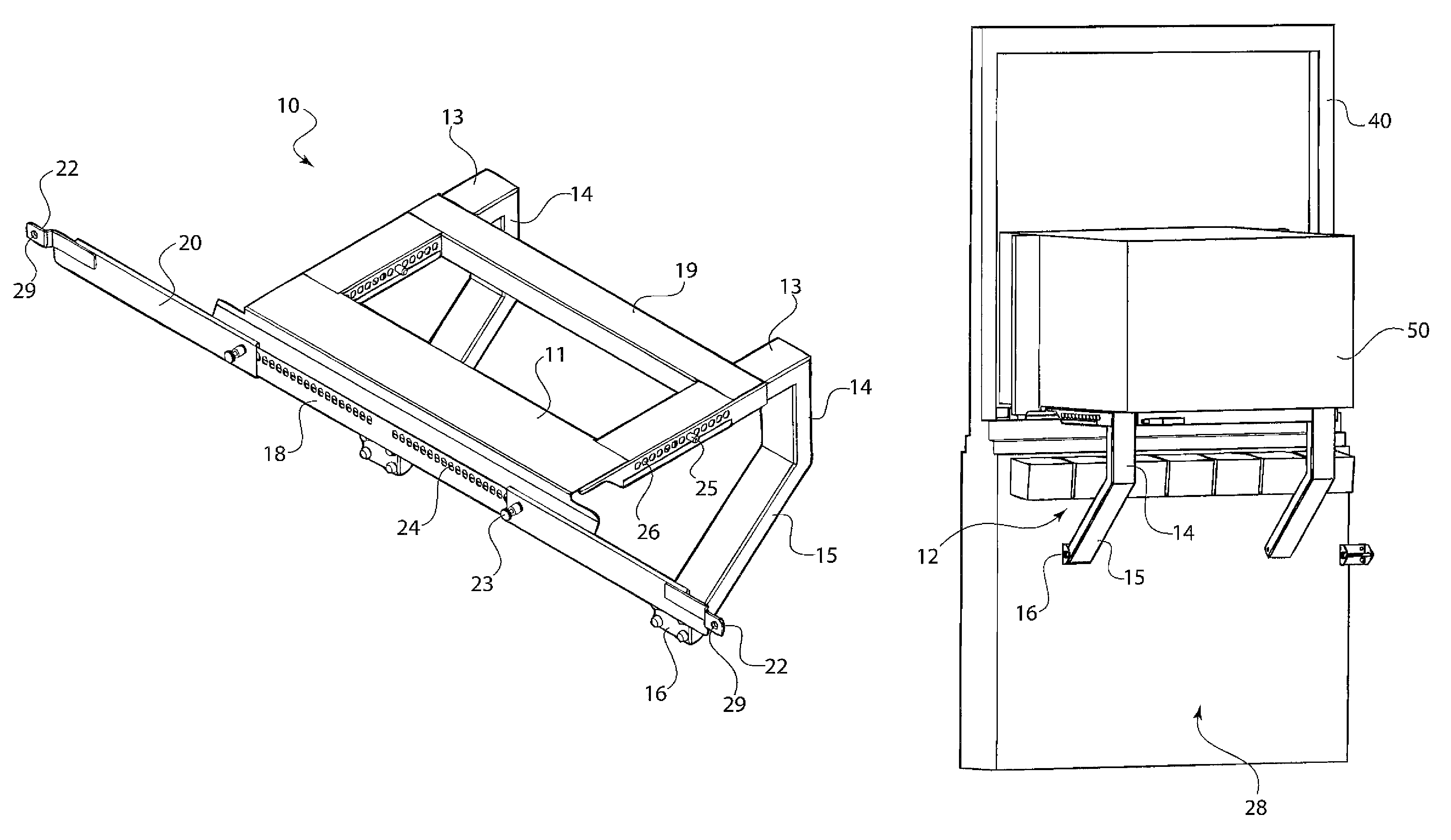
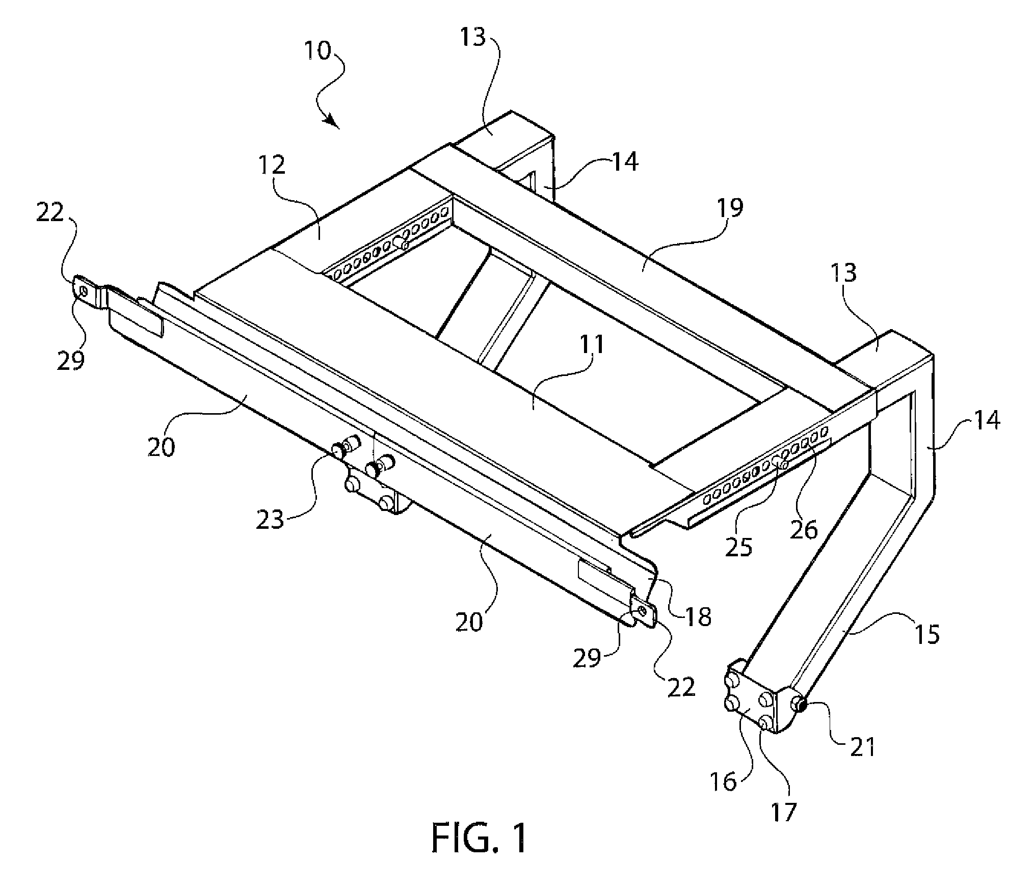
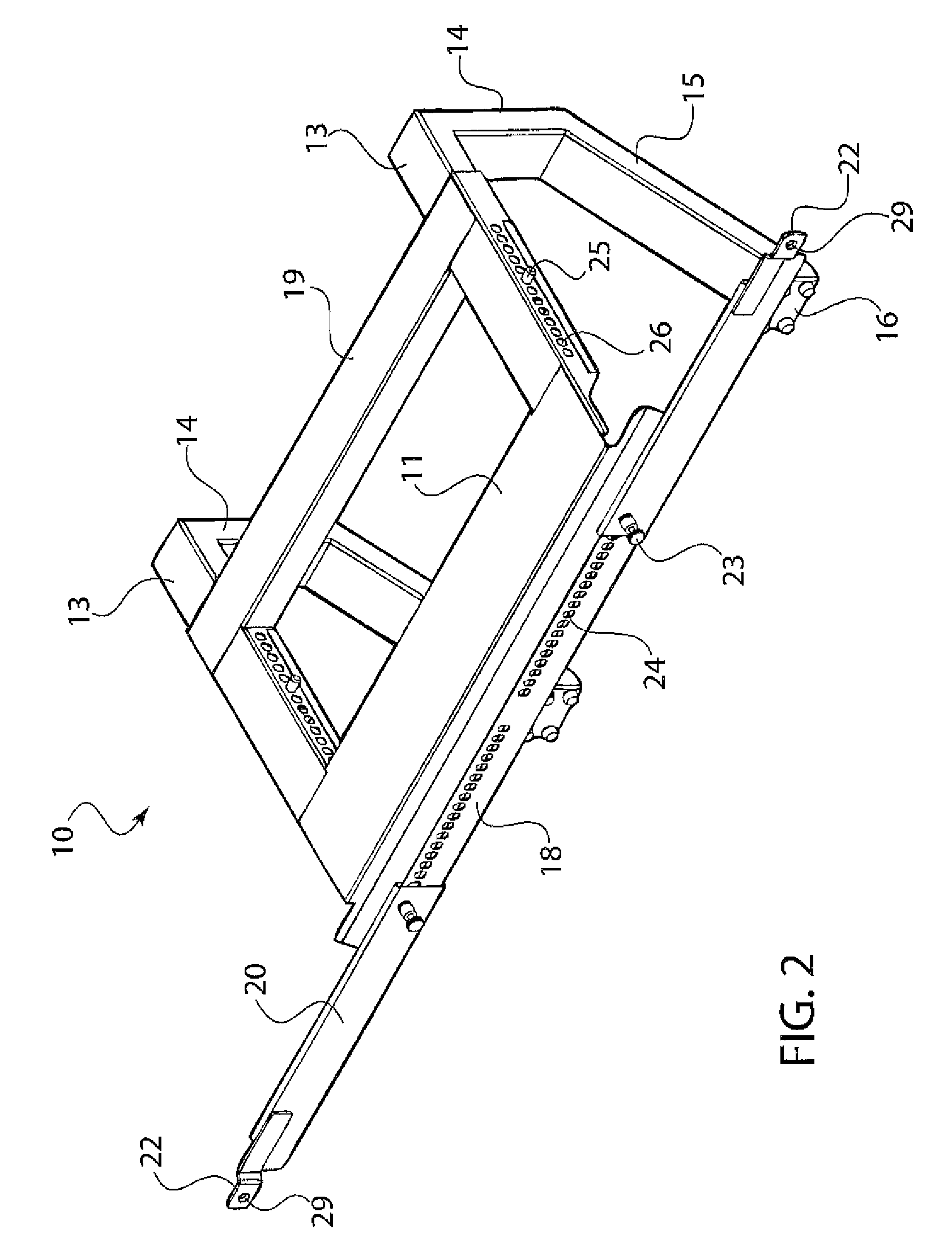
[0031]Referring now in detail to the drawings and, in particular, FIGS. 1 and 2 show a top view of bracket 10 according to the invention. Bracket 10 comprises a base plate 11 connected to two support legs 12, which are formed by a horizontal portion 13, a vertical portion 14 and a slanted portion 15, all connected together. An end face 16 is connected to the end of slanted portion 15, in a pivotable manner, via screw 21. End caps 17 are affixed around the surface of end face 16 to aid in positioning end face 16 against a wall, as will be described later. Crosspiece 19 connects support legs 12 to provide extra stability as well as extra support for the air conditioner.

[0032]Connected to the front edge of base plate 11 is a front trough 18, which has two slidable extension arms 20, secured by spring-loaded pins 23. As shown in FIG. 2, arms 20 are configured to slide outward and be fixed in position by releasing pins 23 at a desired location, where they then seat into one of holes 24 i...


PUM


Abstract

A bracket for mounting an air conditioning unit in a window has a base plate having a front edge and a rear edge and a pair of support legs connected to the base plate and extending from the rear edge, each support leg having an end face that faces in a same direction as the front edge and a support trough connected to the front edge. There are adjustable arms connected to the support trough. These arms are slidable in opposite directions to increase the width of the bracket and fit it exactly to the width of the window frame. When the bracket is positioned in a window frame of a structure, the support trough fits within the window frame and the end faces of the each support leg rest against an exterior of the structure.

Description

CROSS REFERENCE TO RELATED APPLICATIONS[0001]Applicant claims priority under 35 U.S.C. §119(e) of U.S. Provisional Patent Application No. 61 / 888,163 filed Oct. 8, 2013, the disclosure of which is incorporated by reference.BACKGROUND OF THE INVENTION[0002]1. Field of the Invention[0003]The present invention relates to a bracket for mounting a window air conditioner unit, and a method for mounting the air conditioning unit in a window. In particular, the invention relates to a bracket that enables air conditioners of various sizes to be securely mounted in a window frame without the need for shims or other adjustment devices.[0004]2. The Prior Art[0005]Window air conditioners are commonly used in older buildings that are not equipped with central air conditioning ducts, or in locations where the need for air conditioning is restricted to a very small window of time. These window units are convenient because they can be installed and removed without affecting the building, and can be m...

Claims


Application Information

Patent Timeline
Patent Type & Authority Patents(United States)
IPC IPC(8): F24F13/32A47F3/02E04B1/41E04G3/18E06B7/28F24F1/02E04B1/38
CPCF24F13/32A47F3/02E04B1/40E04G3/18E06B7/28F24F1/027E04B2001/405E04B1/388E04B2001/389
Inventor ARBUCCI, ERNEST
Owner TOPSHELF A C
Learn More