
Box-frame housing and a method of manufacture

a box-frame and box-frame technology, applied in the direction of manufacturing tools, casings/cabinets/drawers, electrical equipment casings/cabinets/drawers, etc., can solve the problem of limited free space for opening the box-frame housing, and achieve the effect of preventing bending or bulging of the side wall, short manufacturing time and promoting the stability of the box-frame housing

Active Publication Date: 2015-10-20
ROHDE & SCHWARZ GMBH & CO KG
View PDF30 Cites 2 Cited by
  • Summary
  • Abstract
  • Description
  • Claims
  • Application Information

AI Technical Summary

Benefits of technology

[0007]Embodiments of the present invention advantageously provide a housing for electronic modules with various subdivisions into sub-regions, which can be manufactured in a simple and cost favorable manner, and which is readily accessible for fitting and maintenance, and a corresponding manufacturing method.
[0008]Embodiments of the box-frame housing for the installation of electronic modules comprise frame elements and side walls and provides a subdivision into sub-regions which are limited by dividing walls, wherein the frame elements and the side walls and dividing walls provide at least one recess and / or at least one edge projection; a projection engages in a recess; and the projection and the recess are connected to one another by welding. An extremely diverse range of subdivisions of the box-frame housing can be advantageously achieved through the positioning of the recesses and the corresponding edge projections. The individual side walls and dividing walls can be plugged together simply and form a stable structure even before the welding process. This simplifies the clamping of the individual parts in preparation for the subsequent welding process. This achieves a short pre-clamping time and accordingly an optimized assembly time.
[0009]An intermediate space between the projection and an edge of the recess into which the projection engages advantageously provides a width of less than 100 μm, preferably less than 50 μm. The resulting tolerances for the size of the projection and the recesses can be achieved without difficulty with currently conventional punching or laser-cutting technology. Accordingly, conventional punching or cutting techniques can be used for the manufacture of the box-frame housing and allow a cost-favorable manufacture.

Problems solved by technology

Moreover, no tools, such as screwdrivers etc, are necessary to release the top panel or base panel, so that only a limited free space is required for opening the box-frame housing.

Method used


Image

  • Box-frame housing and a method of manufacture
  • Box-frame housing and a method of manufacture
  • Box-frame housing and a method of manufacture

Examples


Embodiment Construction

[0040]Parts corresponding to one another are provided with the same reference numbers in all of the drawings.

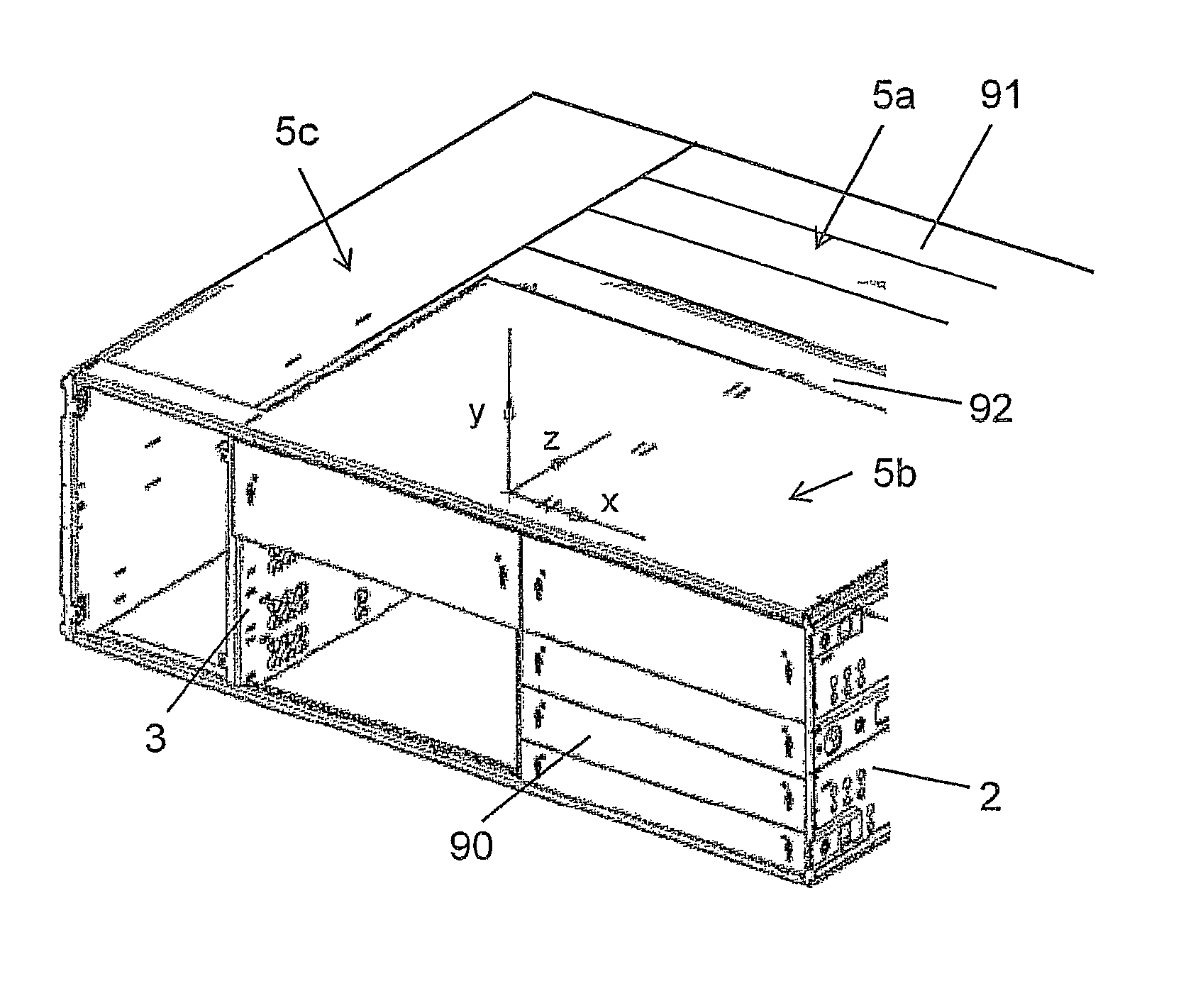
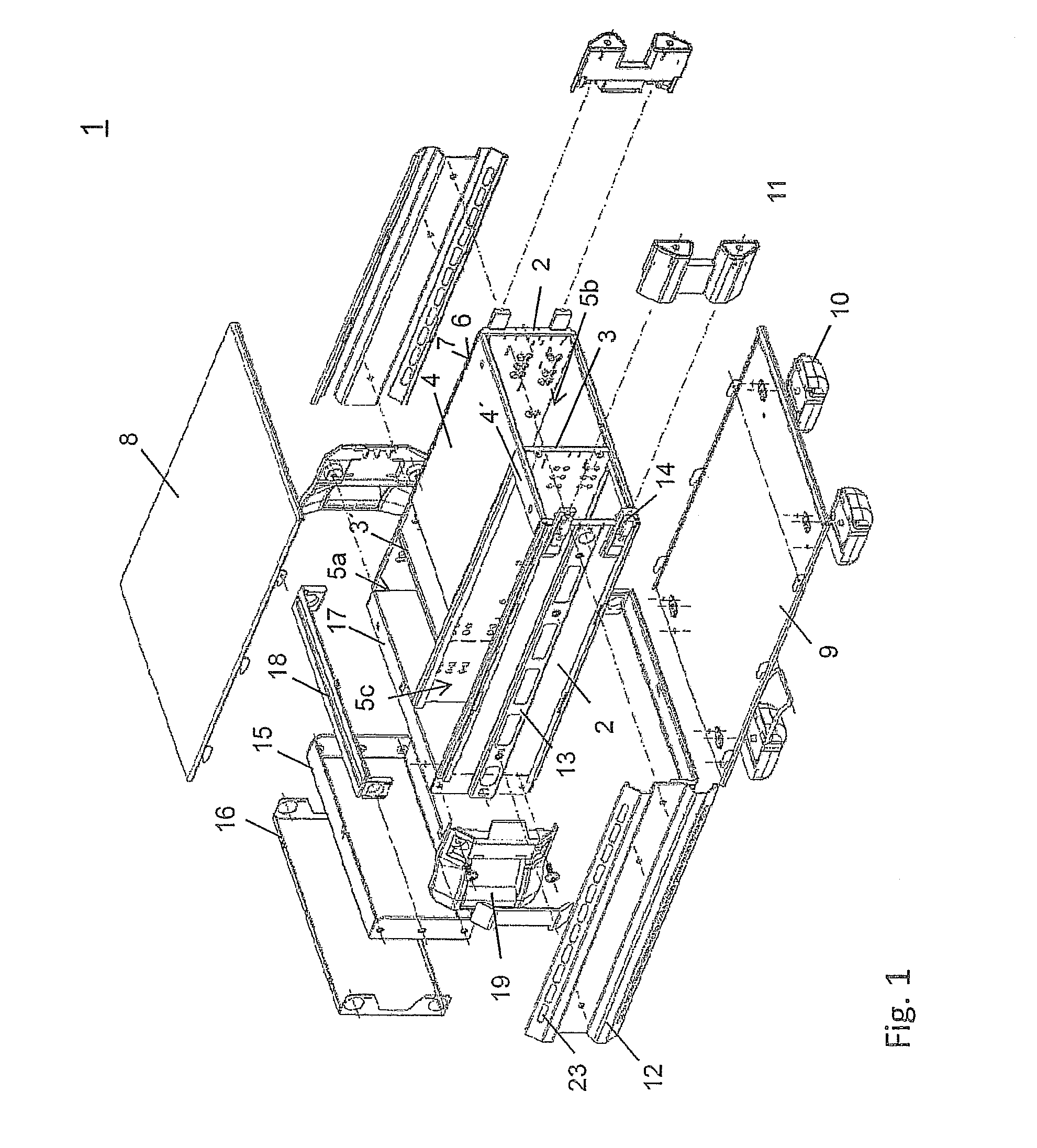
[0041]FIG. 1 shows an overview of the components of a box-frame housing 1 according to the invention. The base element of the housing provides two side walls 2, one or more dividing walls 3 and frame elements 4, which can be punched out as flat frame elements 4 or stepped frame elements 4′ or also as front frame elements 17. Different sub-regions 5a, 5b, 5c in the box-frame housing are formed either by the dividing walls 3 aligned parallel to the side wall 2 and / or by the dividing wall 3′ aligned perpendicular to the side walls 2. The side walls and dividing walls, the frame elements, a top panel and a base panel 8, 9 are manufactured from a metal sheet, preferably a stainless steel sheet.

[0042]The top panel 8 and the base panel 9 enclose the basic housing element. The structural elements inserted into the sub-regions are additionally electromagnetically shielded by a metalli...


PUM

PropertyMeasurementUnit
widthaaaaaaaaaa
widthaaaaaaaaaa
distanceaaaaaaaaaa

Abstract

A box-frame housing for the installation of electronic modules has frame elements and side walls and provides a subdivision into sub-regions, which are limited by dividing walls. The frame elements and the side walls and dividing walls provide at least one recess and / or at least one edge projection. A projection engages in a recess and both are connected to one another by welding.

Description

CROSS-REFERENCE TO RELATED APPLICATION[0001]The present application is a national phase application of PCT Application No. PCT / EP2011 / 063367, filed on Aug. 3, 2011, and claims priority to German Application No. DE 10 2010 035 100.8, filed on Aug. 23, 2010, and German Application No. DE 10 2010 049 605.7, filed on Oct. 26, 2010, the entire contents of which are herein incorporated by reference.BACKGROUND OF THE INVENTION[0002]1. Field of the Invention[0003]The invention relates to a box-frame housing for the installation of electronic modules with a subdivision into sub-regions and a method for its manufacture.[0004]2. Discussion of the Background[0005]Document DE 196 03 368 A1 describes a box-frame housing for electronic measuring devices of a design conventional at the time. The box-frame housing described comprises an enclosed rectangular frame, a rack-shelf mount with a flat base and narrow side walls projecting at right angles from it, which accommodate the operating elements of...

Claims


Application Information

Patent Timeline
Patent Type & Authority Patents(United States)
IPC IPC(8): H05K7/14H05K5/04H05K9/00H05K5/02H05K13/00
CPCH05K5/0213H05K5/04H05K7/1418H05K9/0016H05K13/00H05K7/14H05K7/1424Y10T29/49833Y10T29/49904B23K33/00
Inventor MUHR, HERMANNFISCHL, ANDREASKUFER, WOLFGANGKOENIG, HANS-DIETERHINGRAINER, HELMUT
Owner ROHDE & SCHWARZ GMBH & CO KG
Learn More