Box-frame housing and a method of manufacture

Active Publication Date: 2013-06-13
ROHDE & SCHWARZ GMBH & CO KG
View PDF14 Cites 5 Cited by
  • Summary
  • Abstract
  • Description
  • Claims
  • Application Information

AI Technical Summary

Benefits of technology

[0019]It is particularly advantageous if the side walls and dividing walls provide one or more ventilation zones, in each case with a plurality of ventilation openings, and a transverse embossing is introduced into the side wall and/or dividing wall in the region of the ventilation zone, transversely to one edge of the side wall and/or dividing wall. This prevents a bending or bulging of the side wall by punching out the ventilation openings and promotes the stability of the box-frame housing.
[0020]It is also advantageous if

Problems solved by technology

Moreover, no tools, such as screwdrivers etc, are necessary to release the top panel or ba

Method used


Image

  • Box-frame housing and a method of manufacture
  • Box-frame housing and a method of manufacture
  • Box-frame housing and a method of manufacture

Examples


Embodiment Construction

[0040]Parts corresponding to one another are provided with the same reference numbers in all of the drawings.

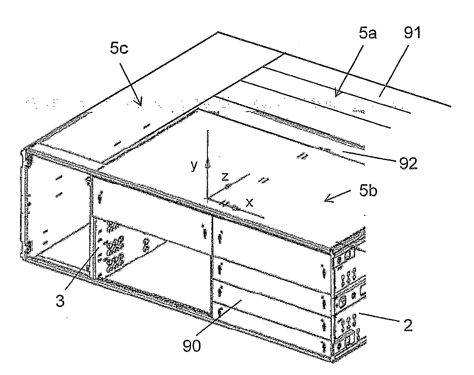
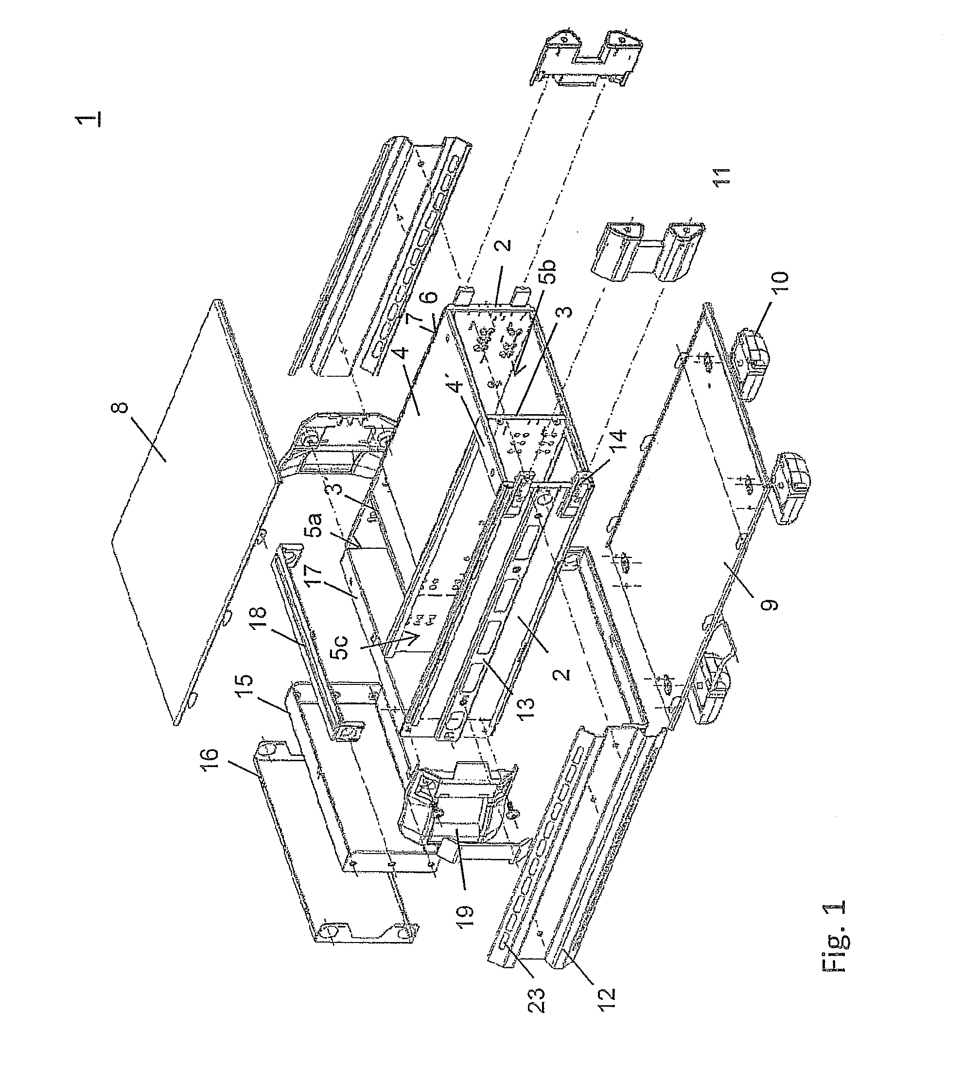
[0041]FIG. 1 shows an overview of the components of a box-frame housing 1 according to the invention. The base element of the housing provides two side walls 2, one or more dividing walls 3 and frame elements 4, which can be punched out as flat frame elements 4 or stepped frame elements 4′ or also as front frame elements 17. Different sub-regions 5a, 5b, 5c in the box-frame housing are formed either by the dividing walls 3 aligned parallel to the side wall 2 and / or by the dividing wall 3′ aligned perpendicular to the side walls 2. The side walls and dividing walls, the frame elements, a top panel and a base panel 8, 9 are manufactured from a metal sheet, preferably a stainless steel sheet.

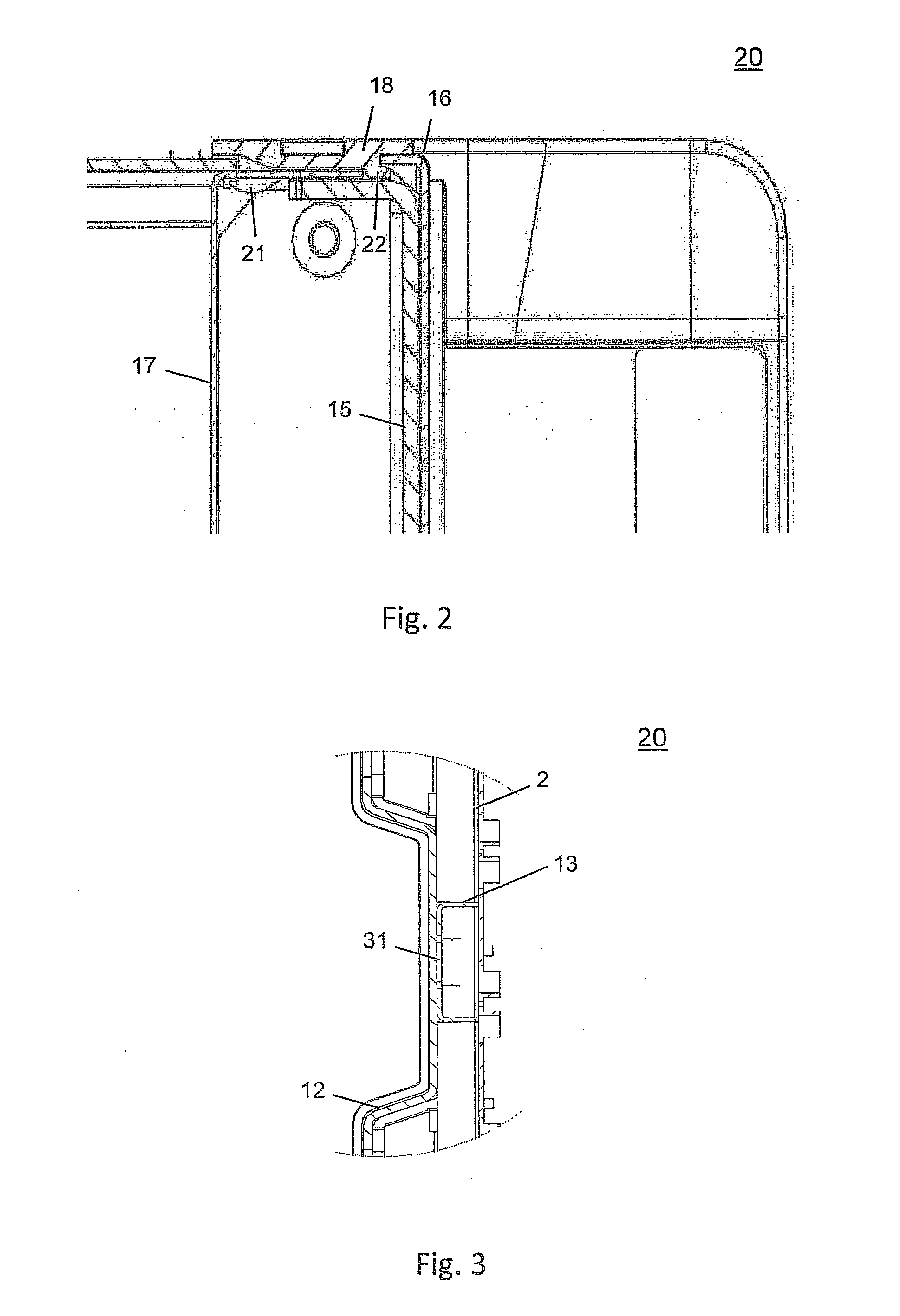
[0042]The top panel 8 and the base panel 9 enclose the basic housing element. The structural elements inserted into the sub-regions are additionally electromagnetically shielded by a metalli...


PUM

PropertyMeasurementUnit
Timeaaaaaaaaaa
Lengthaaaaaaaaaa
Lengthaaaaaaaaaa

Abstract

A box-frame housing for the installation of electronic modules has frame elements and side walls and provides a subdivision into sub-regions, which are limited by dividing walls. The frame elements and the side walls and dividing walls provide at least one recess and/or at least one edge projection. A projection engages in a recess and both are connected to one another by welding.

Description

CROSS-REFERENCE TO RELATED APPLICATION[0001]The present application is a national phase application of PCT Application No. PCT / EP2011 / 063367, filed on Aug. 3, 2011, and claims priority to German Application No. DE 10 2010 035 100.8, filed on Aug. 23, 2010, and German Application No. DE 10 2010 049 605.7, filed on Oct. 26, 2010, the entire contents of which are herein incorporated by reference.BACKGROUND OF THE INVENTION[0002]1. Field of the Invention[0003]The invention relates to a box-frame housing for the installation of electronic modules with a subdivision into sub-regions and a method for its manufacture.[0004]2. Discussion of the Background[0005]Document DE 196 03 368 A1 describes a box-frame housing for electronic measuring devices of a design conventional at the time. The box-frame housing described comprises an enclosed rectangular frame, a rack-shelf mount with a flat base and narrow side walls projecting at right angles from it, which accommodate the operating elements of...

Claims


Application Information

Patent Timeline
IPC IPC(8): H05K7/14H05K5/04H05K13/00H05K5/02
CPCH05K5/04H05K7/1418H05K13/00H05K5/0213H05K7/14H05K9/0016H05K7/1424Y10T29/49833Y10T29/49904B23K33/00
Inventor MUHR, HERMANNFISCHL, ANDREASKUFER, WOLFGANGKOENIG, HANS-DIETERHINGRAINER, HELMUT
Owner ROHDE & SCHWARZ GMBH & CO KG
Why Eureka
Try Eureka