Printer cartridge having a retractable mechanism

a technology of retractable mechanism and printing cartridge, which is applied in the direction of optics, instruments, electrography/magnetography, etc., can solve the problems of affecting the engagement between the driving force receiver and the driving member of the image forming device, and achieve the effect of greatly improving the reliability of the retractable mechanism

Active Publication Date: 2015-11-03
NINESTAR CORP
View PDF8 Cites 17 Cited by
  • Summary
  • Abstract
  • Description
  • Claims
  • Application Information

AI Technical Summary

Benefits of technology

[0028]By adoption of the technical proposal, due to the addition of the control mechanism for controlling the extension and retraction of the retractable mechanism, the extension and retraction of the driving force receiving opening can be controlled just by controlling the extension and retraction of the retractable mechanism through the control mechanism when the driving force receiving opening and a driving mechanism for an image forming device begin to get engaged and disengaged, thus the driving force receiving opening and the driving mechanism for the image forming device can be kept in a straight line when beginning to get engaged and disengaged, consequently the engagement between the driving force receiving opening and the driving mechanism for the image forming device cannot be affected by the friction damage when meeting a bevel. Therefore, the technical problem, that the engagement between the driving force receiving opening for the traditional process cartridge and the driving mechanism for the image forming device is affected by the friction damage when meeting the bevel when beginning to get engaged and disengaged, is solved. Moreover, the control mechanism has two modes, namely mechanical control and solenoid-valve control, so that users not only can select the safe and reliable mechanical control mode as required but also can select the solenoid-valve control mode according to the requirement of automatic control. Meanwhile, the invention also provides a plurality of reliable retractable mechanisms, so that the reliability of the retractable mechanisms is greatly improved.

Problems solved by technology

However, due to the flexible pressure device, the driving force receiver, namely the driving force receiving opening, is always in the pressurized state when beginning to get engaged and disengaged with a driving mechanism of the image forming device, thus the driving force receiver and the driving member for the image forming device cannot be kept in a straight line when beginning to get engaged and disengaged as the inner space of the image forming device is limited, consequently the driving force receiver and the driving member of the image forming device are inevitably subjected to the friction damage when meeting a bevel when beginning to get engaged and disengaged and then the engagement between the driving force receiver and the driving member of the image forming device is affected.

Method used


Image

  • Printer cartridge having a retractable mechanism
  • Printer cartridge having a retractable mechanism
  • Printer cartridge having a retractable mechanism

Examples


first embodiment

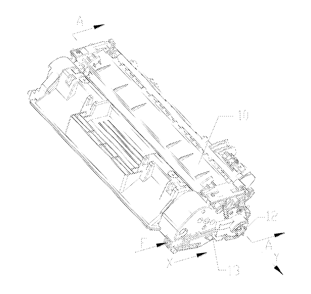
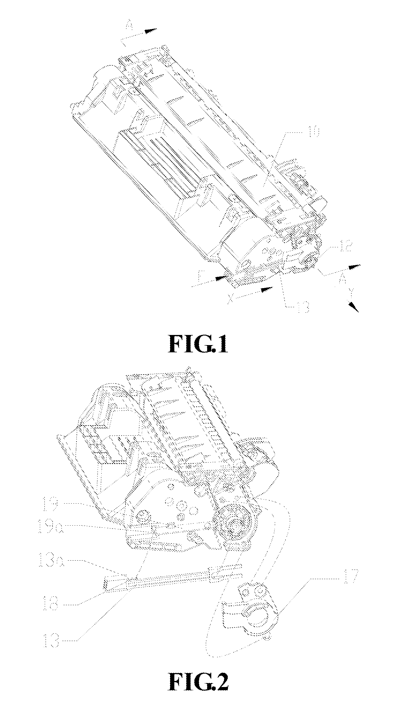
[0059]FIG. 1 is a stereogram of a process cartridge of a preferred embodiment of the invention, and FIG. 2 is an exploded view of the process cartridge illustrated in FIG. 1. As illustrated in FIG. 2, a press rod 13 and a first spring 18 are arranged at one side of a process cartridge housing 10, where a driving force receiving opening 12 is arranged; the press rod 13 and the first spring 18 are combined into a control mechanism; the press rod 13 is arranged inside a guide groove 19 on the process cartridge housing 10 and slides back and forth along the guide groove 19 in the X direction; and the first spring 18 leans against a space between an urging surface 13a of the press rod 13 and a leaning surface 19a of the guide groove 19 and provides an elastic restoring force for the press rod 13. When the process cartridge is positioned on an image forming device, the urging surface 13a of the press rod 13 tends to be far away from the leaning surface 19a when the press rod 13 is under t...

second embodiment

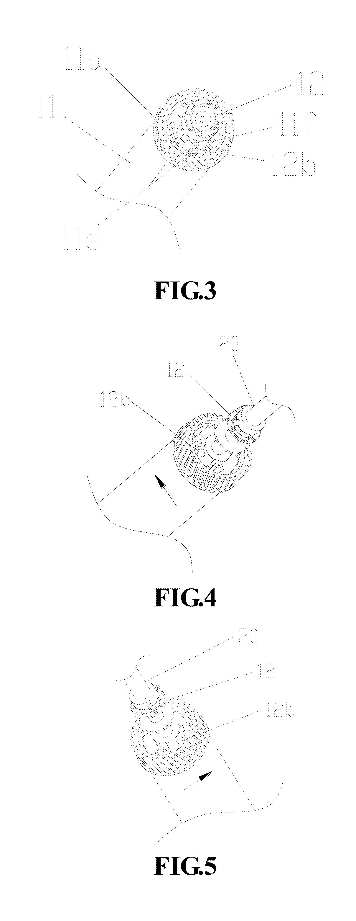
[0070]In the above embodiment, only the driving force receiving opening 12 can be driven by the press rod 13 to extend or retract in the axial direction of the photosensitive member 11 so as to engage or disengage with the driving mechanism 20 on the image forming device. It can be understood that a retractable mechanism in this embodiment can also adopt the mode that a driving force receiving opening 12 and a photosensitive member 11 are integrated into a whole and extended or retracted together, and the engagement and disengagement of the driving force receiving opening 12 and the driving mechanism 20 on the image forming device is controlled by a press rod 13. The structures which are the same with those of the first embodiment (such as a control mechanism) are not described in detail here.

[0071]The structure and the working process of the retractable mechanism are as follows:

[0072]As illustrated in FIG. 9, a shaft pin 14 and a support 17 are arranged on a process cartridge housi...

third embodiment

[0074]The structure and the operating process of a retractable mechanism in the embodiment, which is the same with those of the first and second embodiments, are not repeated here.

[0075]In the invention, the retraction of the driving force receiving opening can not only be realized by a mechanical press mode but also can be controlled by an electromechanical mode. The implementation of a control mechanism is as follows:

[0076]As illustrated in FIG. 15, the embodiment adopts a single-coil solenoid valve 4d to control the engagement and disengagement of a driving force receiving opening 5d at the driven side of a connecter 14d and a driving mechanism 6d of an image forming device. The driving force receiving opening 5d is arranged at one end of a shaft 8d of the connector 14d, and the other end of the shaft 8d of the connector 14d passes through a hollow cylinder of the solenoid valve 4d and can move left or right relative to the solenoid valve; the solenoid valve 4d is fixed on a proc...


PUM


Abstract

The invention relates to a process cartridge, which comprises a process cartridge housing, a photosensitive member, a driving force receiving opening, a retractable mechanism and a control mechanism, wherein the photosensitive member is arranged inside the process cartridge housing; the driving force receiving opening is connected with the photosensitive member and provides a driving force for the photosensitive member; the retractable mechanism allows the driving force receiving opening to extend or retract in the axial direction of the photosensitive member; and the control mechanism controls the extension and retraction of the retractable mechanism.

Description

CROSS-REFERENCE TO RELATED APPLICATIONS[0001]This is a continuation-in-part application of International Application PCT / CN2010 / 079377, with an international filing date of Dec. 2, 2010, currently pending, and claims priority to Chinese Patent Application No. 201010104692.6, Jan. 28, 2010, and Chinese Patent Application No. 201010131386.1, filed Mar. 22, 2010.FIELD OF THE INVENTION[0002]The invention relates to an image forming device based on electrostatic printing technology, in particular to a process cartridge applied to the same.BACKGROUND OF THE INVENTION[0003]The invention relates to a process cartridge which is detachably arranged on an image forming device based on electrostatic printing technology, wherein the image forming device can be any one of a laser image forming device, an LED image forming device, a copier or a facsimile apparatus.[0004]The working process of the image forming device based on the electrostatic printing technology is as follows: firstly, predetermi...

Claims


Application Information

Patent Timeline
Patent Type & Authority Patents(United States)
IPC IPC(8): G03G21/00G03G21/18
CPCG03G21/1857G03G21/186
Inventor GU, WEIDONGDING, GEMINGLI, YONGHONGLI, ZHIYONGCAO, JIANXINLI, XIONGLIU, XIAOBING
Owner NINESTAR CORP
Why Eureka
Try Eureka