
Image sensor with optical filters having alternating polarization for 3D imaging

a technology of optical filters and image sensors, applied in the field of image sensors, can solve problems such as increasing pixel crosstalk

Active Publication Date: 2015-11-03
OMNIVISION TECH INC
View PDF22 Cites 7 Cited by
  • Summary
  • Abstract
  • Description
  • Claims
  • Application Information

AI Technical Summary

Benefits of technology

The patent describes an image sensor that uses optical filters with alternating polarization to capture 3D images. The sensor includes a single image sensor with multiple pixel circuits that capture the left and right views of an image. The left and right views are then separated using a lenticular-lens or micro-lens array, which may increase pixel crosstalk and introduce crosstalk between the left and right images. The invention provides a solution to this problem by using a single image sensor with alternating polarization filters on each pixel, which reduces crosstalk and improves the quality of 3D imaging.

Problems solved by technology

However, the interleaving using a lenticular-lens or micro-lens array may increase pixel crosstalk and may also introduce crosstalk between the captured left and right images.

Method used


Image

  • Image sensor with optical filters having alternating polarization for 3D imaging
  • Image sensor with optical filters having alternating polarization for 3D imaging
  • Image sensor with optical filters having alternating polarization for 3D imaging

Examples


Embodiment Construction

[0018]Embodiments of an Image Sensor with Optical Filters having Alternating Polarization for 3D Imaging are described herein. In the following description numerous specific details are set forth to provide a thorough understanding of the embodiments. One skilled in the relevant art will recognize, however, that the techniques described herein can be practiced without one or more of the specific details, or with other methods, components, materials, etc. In other instances, well-known structures, materials, or operations are not shown or described in detail to avoid obscuring certain aspects.

[0019]Reference throughout this specification to “one embodiment” or “an embodiment” means that a particular feature, structure, or characteristic described in connection with the embodiment is included in at least one embodiment of the present invention. Thus, the appearances of the phrases “in one embodiment” or “in an embodiment” in various places throughout this specification are not necessa...


PUM


Abstract

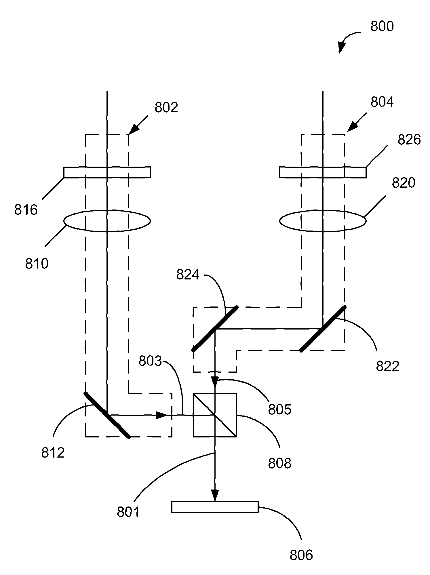
An image sensor for three-dimensional (“3D”) imaging includes a first, a second, and a third pixel unit, where the second pixel unit is disposed between the first and third pixel units. Optical filters included in the pixel units are disposed on a light incident side of the image sensor to filter polarization-encoded light having a first polarization and a second polarization to photosensing regions of the pixel units. The first pixel unit includes a first optical filter having the first polarization, the second pixel unit includes a second optical filter having the second polarization, and the third pixel unit includes a third optical filter having the first polarization.

Description

TECHNICAL FIELD[0001]This disclosure relates generally to image sensors, and in particular but not exclusively, relates to 3D image sensors.BACKGROUND INFORMATION[0002]Recently, three-dimensional (3D) movies are played in cinemas and receive a great deal of attention from public. 3D TVs and displays are also available for home use. 3D movies can be played using a 3D DVD player and thus a 3D movie can be watched at home. A 3D display may also be known as a stereoscopic display.[0003]Displaying a 3D image is essentially conducted by allowing the left eye to see a left view only and the right eye to see a right view only. The difference between the left and right views creates a parallax such that the viewer feels as he is seeing a 3D object. To let the left eye see the left view only and the right eye see the right view only both views must be isolated from each other. The left and right views provided by a display may be encoded in time, i.e., alternately displayed. A pair of goggle ...

Claims


Application Information

Patent Timeline
Patent Type & Authority Patents(United States)
IPC IPC(8): H04N13/02H01L27/146H04N5/369G02B30/25H04N25/00
CPCH01L27/14621H01L27/14627H04N5/3696H04N13/0207H04N13/0217H04N13/0257H04N13/218H04N13/257H04N25/134H04N13/207H04N25/702
Inventor KUANG, JIANGTAOWU, DONGHUIDAI, TIEJUNSHAN, JIZHANG
Owner OMNIVISION TECH INC
Learn More